Assigning loads and constraints to a simulation
Assigning loads and constraints - Exercise
- Open the Hitch.ipt from your working folder.
- In the Environments tab>Begin panel, click Autodesk Inventor Nastran.
- In the Autodesk Inventor Nastran tab>Setup panel, click Loads.
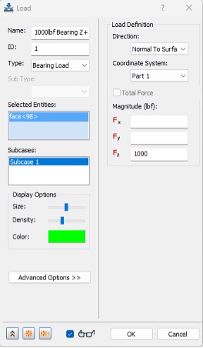
- In the Load dialog box, do the following:
- Set the Type to Bearing Load.
- Right-click in the Selected Entities box and select Select Faces.
- In the model, select the cylindrical surface shown below:
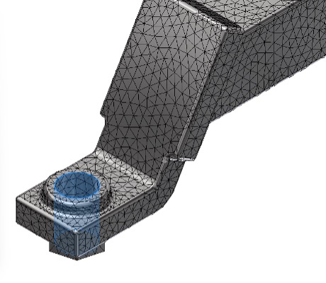
- For the Magnitude (lbf), set Fz to 1000.
- Set the Name to 1000lbf Bearing Z+.
- Click OK.
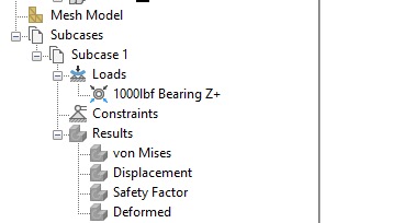
- The load is added to the model. Note that the Bearing Load has also been added to the Loads section in the Nastran Model Tree.
- In the Setup panel, click Loads.
- In the Load dialog box, do the following:
- Set the Type to Gravity.
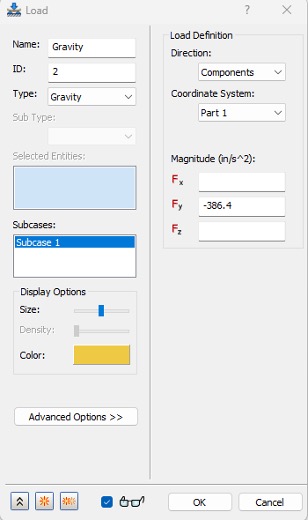
- For the Magnitude (in/s^2), set Fy to -386.4.
- Set the Name to Gravity.
- Click OK.
- In the Nastran Model Tree, right-click on the Total Load subcase and select Duplicate.
- In the Autodesk Inventor Nastran tab>Setup panel, click Constraints.
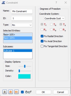
- In the Constraint dialog box, do the following:
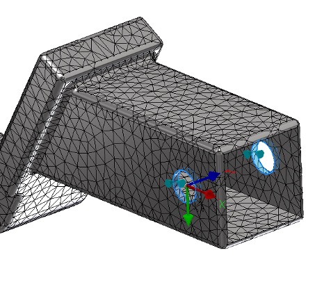
- Set the Type to Pin Constraint.
- Right-click in the Selected Entities box and select Select Faces.
- In the model, select the two cylindrical surfaces shown below:
- Verify that Fix Radial Direction and Fix Axial Direction are checked in the constraints dialog box.
- Change the Name to Pin Constraint.
- Select OK.
- In the Autodesk Inventor Nastran tab>Setup panel, click Constraints.
- In the Constraint dialog box, do the following:
- Set the Type to Structural.
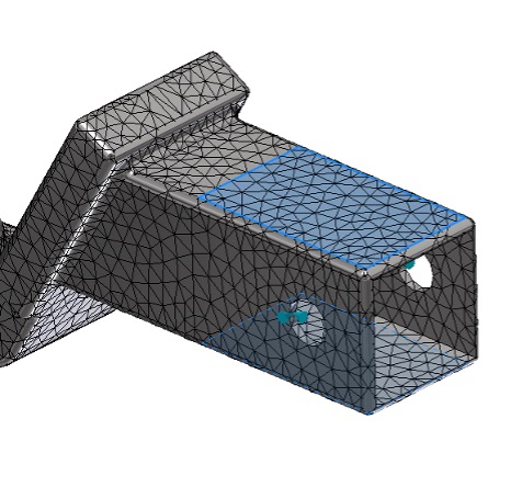
- Right-click in the Selected Entities box and select Select Faces.
- In the model, select the two surfaces shown below:
- Clear all the checkboxes under Degrees of Freedom.
- Check the box for Ty.
- Check the box next to the glasses icon.
- Adjust the Density slider a bit towards the middle.
- Change the Color to Orange.
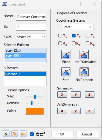
- Change the Name to Receiver Constraint.
- Select OK.
- Save and Close the Model.


