Add pads and piers - Exercise
During these tasks, we shall continue the development of the structural model by adding pads and piers to the sub-structure.
Task 1: Adding pads
During this task we are going to step through a workflow for adding isolated foundations in the form of concrete pads and concrete pads with an included pier.
- Open the project STRUCTURAL (Creating Sub-structure Pads & Piers Start).rvt.
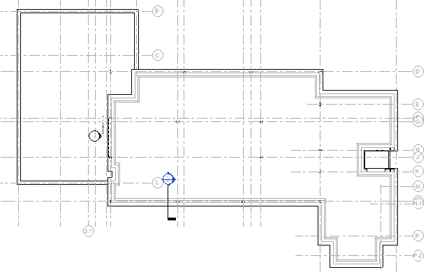
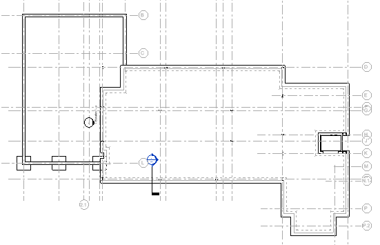
- Open the Ground Floor view in which the ARCHITECTURAL and MEP links have been switched off and we are using the bearing walls and grid lines to indicate where the pads should be added.
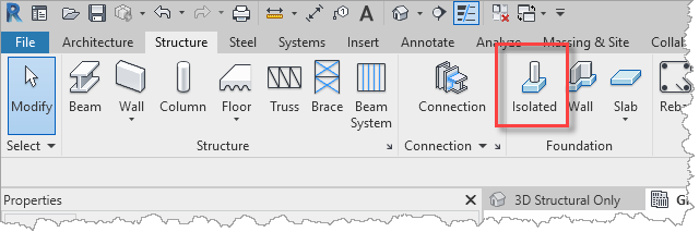
- To add simple pads, select Isolated from the Foundation panel on the Structure ribbon.
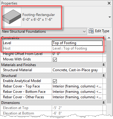
- In the Properties palette, select the Footing-Rectangular 6'-0" x 6'-0" x 1'-6" foundation type. Then select Top of Footing for the Level as we shall be placing the pad aligned with its top.
- Place a number of pads under the bearing wall in the lower level of the building.
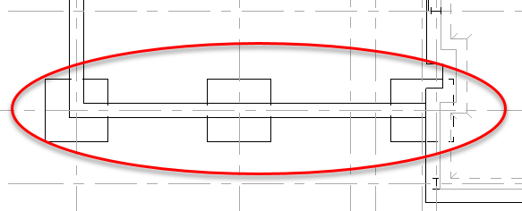
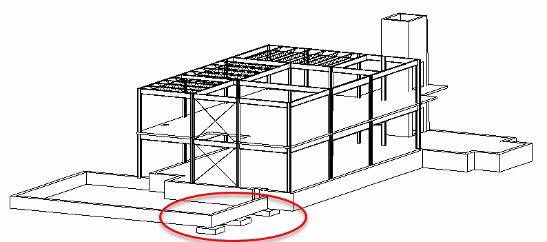
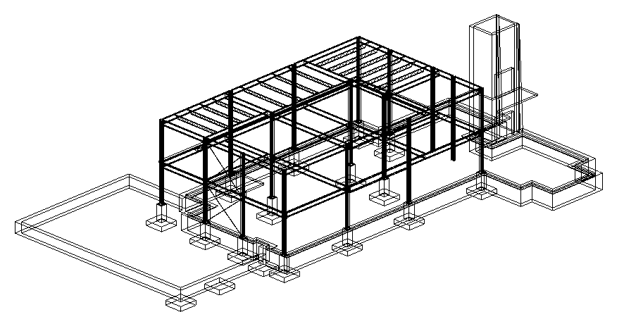
- In the 3D Structural Only view, the model has the pads placed under the bearing wall.
- Save the project so that it can be used in the next objective which will be to assign pads with combined piers to extend up to the bottoms of the steel columns.
Task 2: Adding piers
Next, we shall place a number of pads that have an included pier to support the steel columns.
- Open the project from the previous task and switch to the Ground Floor plan.
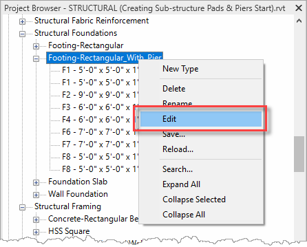
- Before inserting any Revit family, it is worth understanding how it is structured and how it will work once it is placed into a project. The Footing-Rectangular_With_Pier is a case-in-point. Locate the family under Structural Foundations in the Project Browser, right-click, and select Edit from the menu.
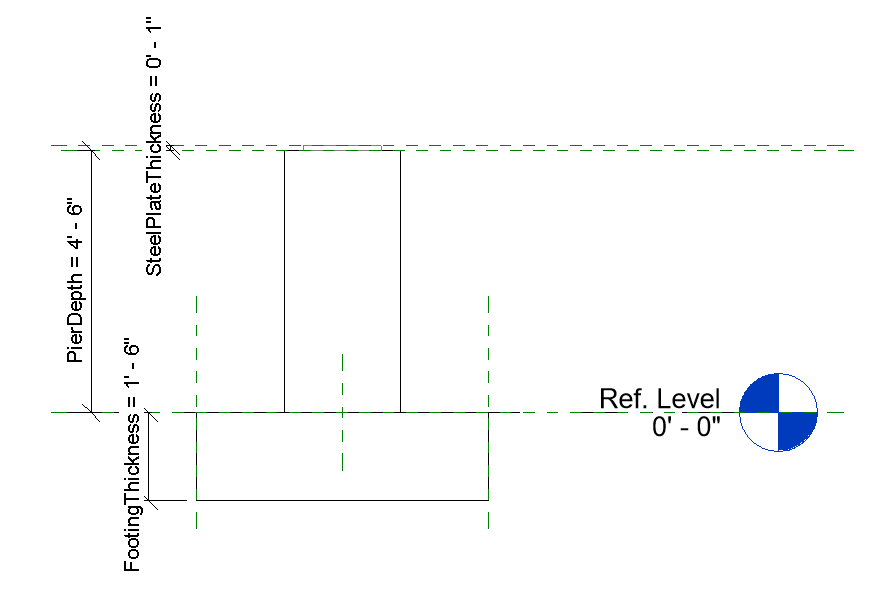
- In the Family Editor, open the Front elevation view of the family. Here we can see that the height of the pier is the total of PierDepth and SteelPlateThickness (interestingly the steel plate has an optional Visible parameter, but not including it does not adjust the total height of the pier).
- Close the Family Editor without saving the family.
- Once again, select Isolated from the Foundation panel on the Structure ribbon.
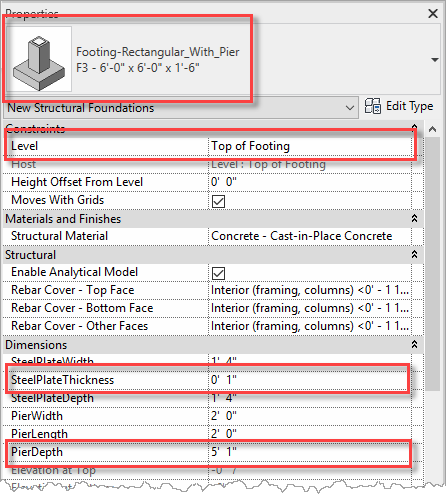
- In the Properties palette, select the Footing-Rectangular_With_Pier F3 - 6'-0" x 6'-0" x 1'-6 foundation type. As explained above, this foundation family needs the height of the pier to be considered. The top of the pad will be inserted at the Top of Footing level which is 5'-2" below Ground Floor. The height of the pier is the total of PierDepth and SteelPlateThickness, so set PierDepth to 5'-1" and SteelPlateThickness to 1".
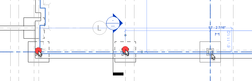
- Simply place a couple of foundations underneath a couple of the columns.
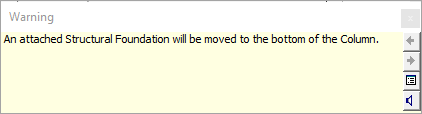
- Note the warning that explains that the bottom of the columns is automatically attached to the foundation.
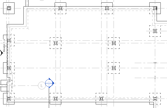
- Add additional piers to the remaining columns.
- Open the 3D Structural Only view and switch to a Wireframe Visual Style to see the piers in 3D.
Task 3: Joining sub-structure
Revit does not automatically merge the piers with the bearing walls, so the next task is to understand how to achieve this by joining the sub-structure geometry.
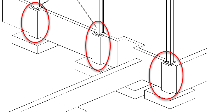
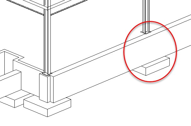
- Open the project from the previous task, switch to the 3D Structural Only view, switch to a Hidden Line Visual Style, and zoom into the corner of the ground floor slab. Notice that there are no join lines between the piers and the 8" Bearing Walls.
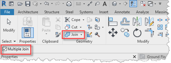
- Whilst this will not impact the structural analysis, it would provide better design-intent if the model was less ambiguous. To resolve this, it is necessary to join the piers with the bearing walls. From the Modify ribbon, select Join that is in the Geometry panel. Since the corner pier overlaps with two bearing walls, enable the Multiple Join option enabled in the Options Bar.
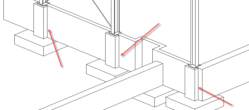
- Simply select each pier in turn, followed by the walls that they should be joined into, for example.
- For the piers in the 16" Bearing Walls, the join requirement is less obvious since the width of the wall is covering up the pier.
- However, switching to the Section 1 – Callout 1 view, it can be seen how the footing is being detailed, with hidden lines indicating a separate (unmerged) component.
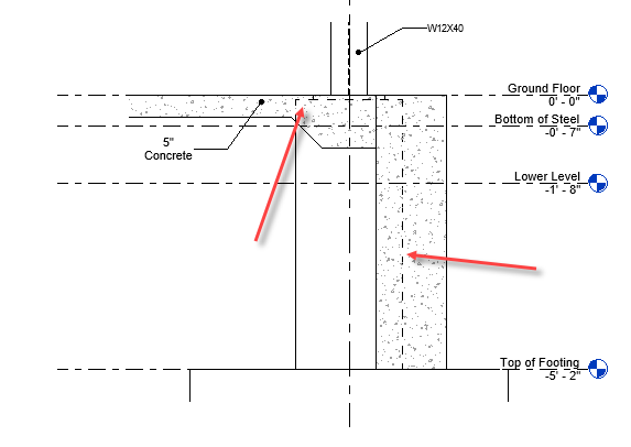
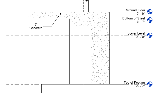
- To merge the pier with the concrete slab, slab edge and bearing wall, use the Join command again on the objects in the detail view, and the hidden lines will be removed.
- Save the project so that it can be used in the next objective which will be to continue the development of the foundations through the inclusion of strip foundations.


