Step-by-step guide
The inline bank is a control object that can be used to act as a connection between 1D and 2D parts of the network. Once bank lines are created and inline bank links are drawn in the direction of flow to intersect these bank lines, the 1D-2D connection can be built.
- Open the transportable database .icmt file for this tutorial.
- In the transportable database window, right-click the top-level folder, and select Copy.
- In the popup, click Continue.
- Right-click the Database and select Paste (with children).
- In the Copying pop-up, enable Copy ground models.
- Click Continue.
- Open 1D/2D River Model and 1m Ground Model on the GeoPlan.
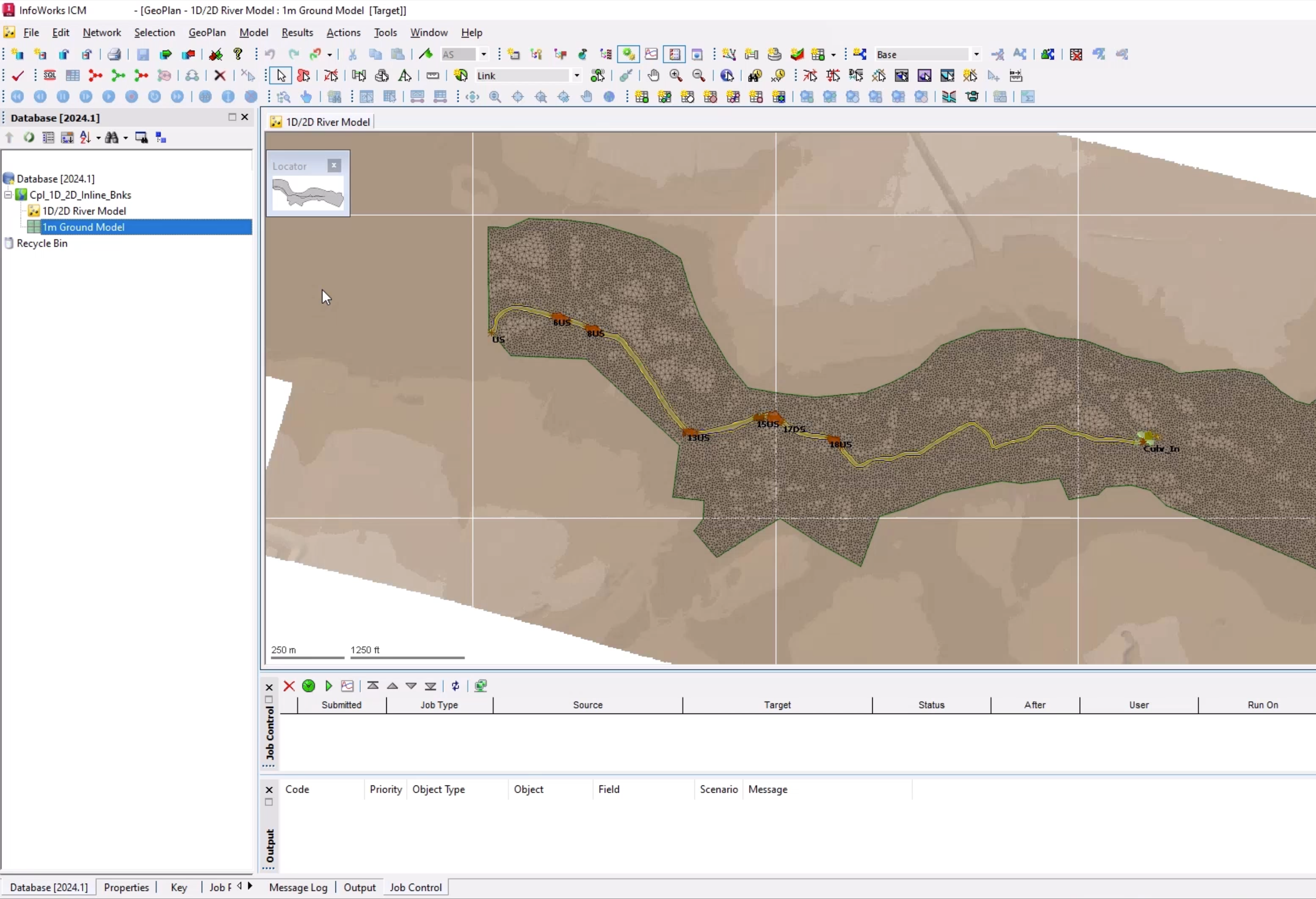
Bank lines and inline banks are already created. This example builds their connection to the 2D zone.
- In the GeoPlan Tools toolbar, click Find in GeoPlan.
- Perform a Quick Find for Culv_Out.
- Once the node is located, Close the Quick Find window.
Building the connection is a simple process that can be done either manually by setting the 2D Zone ID field, or using the inbuilt tool.
To use the tool:
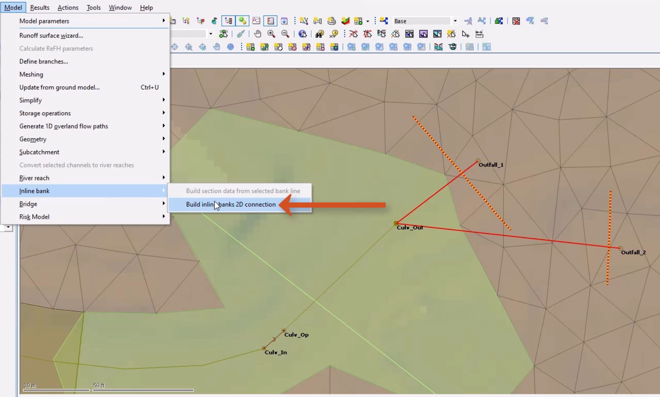
- Make sure that both inline banks are selected.
- From the Model menu, select Inline bank > Build inline banks 2D connection.
To set the outfall levels for the inline banks:
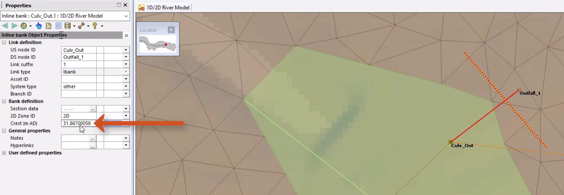
- Double-click the first inline bank to open the Properties window.
- Copy the Crest (m AD) value.
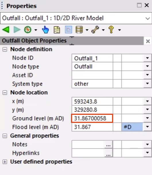
- Double-click the associated outfall node to open the Properties window.
- Paste the value into the Ground level (m AD) field.
- Repeat steps 13-16 for the second inline bank and outfall node.
This process could also be automated via SQL. The object data should now be fully populated for both inline banks without any errors.
Since changes were made, the mesh needs to be regenerated:
- With the 2D zone selected on the GeoPlan, select Model > Meshing > Mesh 2D zones.
- From the Database, drag the 1m Ground Model into the Mesh 2D Zones dialog and drop it into the Ground model group box.
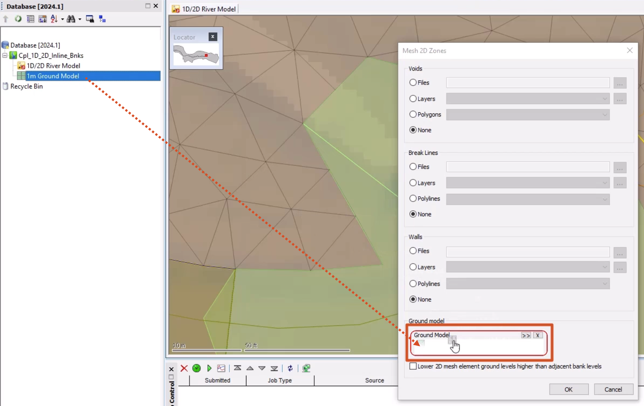
- Click OK.
- In the Schedule Job(s) dialog, click OK.
- Once the mesh has completed, from the Job control window, click the Mesh ready status to open the Manage mesh results dialog box.
- Click Load mesh.
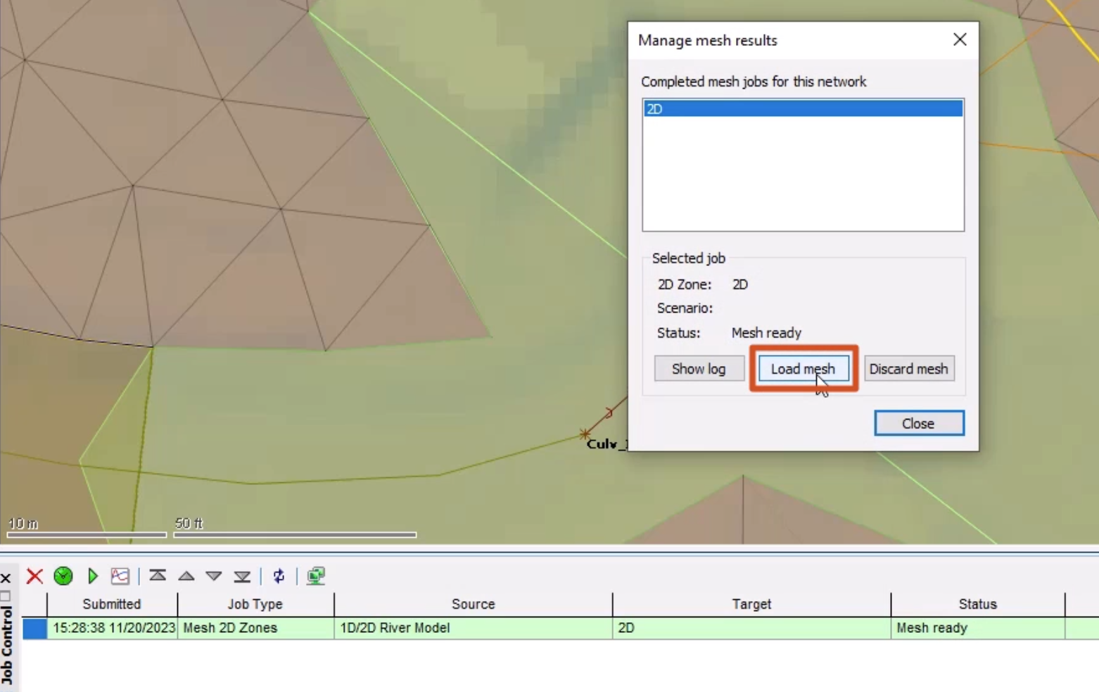
- Click Close.
The bank lines are now correctly connected to the 2D zone.
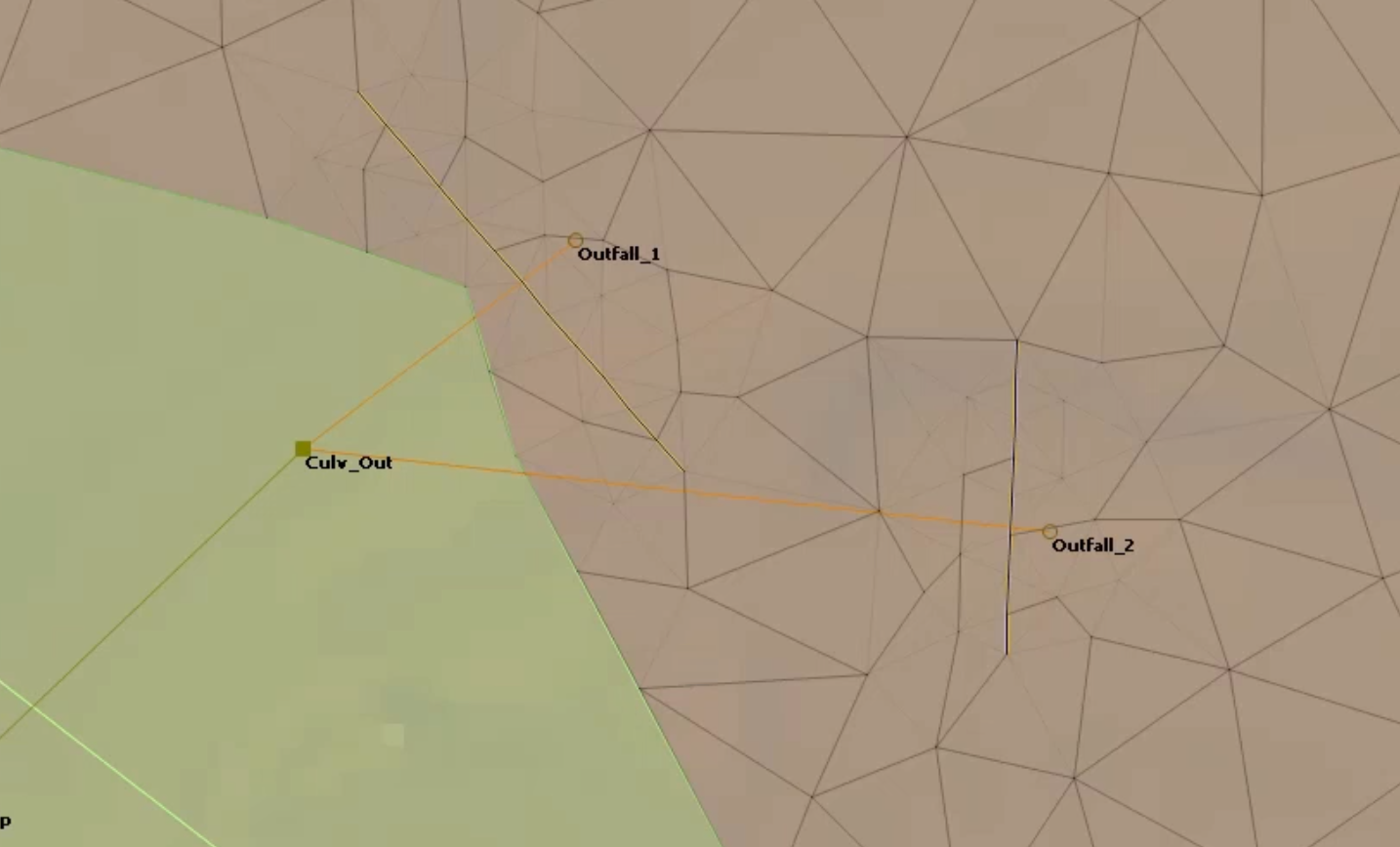
To help visualize the effect that vertices have on the mesh triangle generation and element aggregation:
- Right-click the GeoPlan and select Properties & themes.
- In the Properties and Themes dialog box, switch to the Elements tab.
- Under 2D elements, for Internal edges, click the More (…) button.
- In the Internal Edges Color dialog box, change the color to red.
- Click OK.

- Click OK again to close the Properties and Themes dialog box.
- On the GeoPlan, zoom in to see that many internal edges (triangles) have been generated around the inline banks, as they have vertices every 2m.
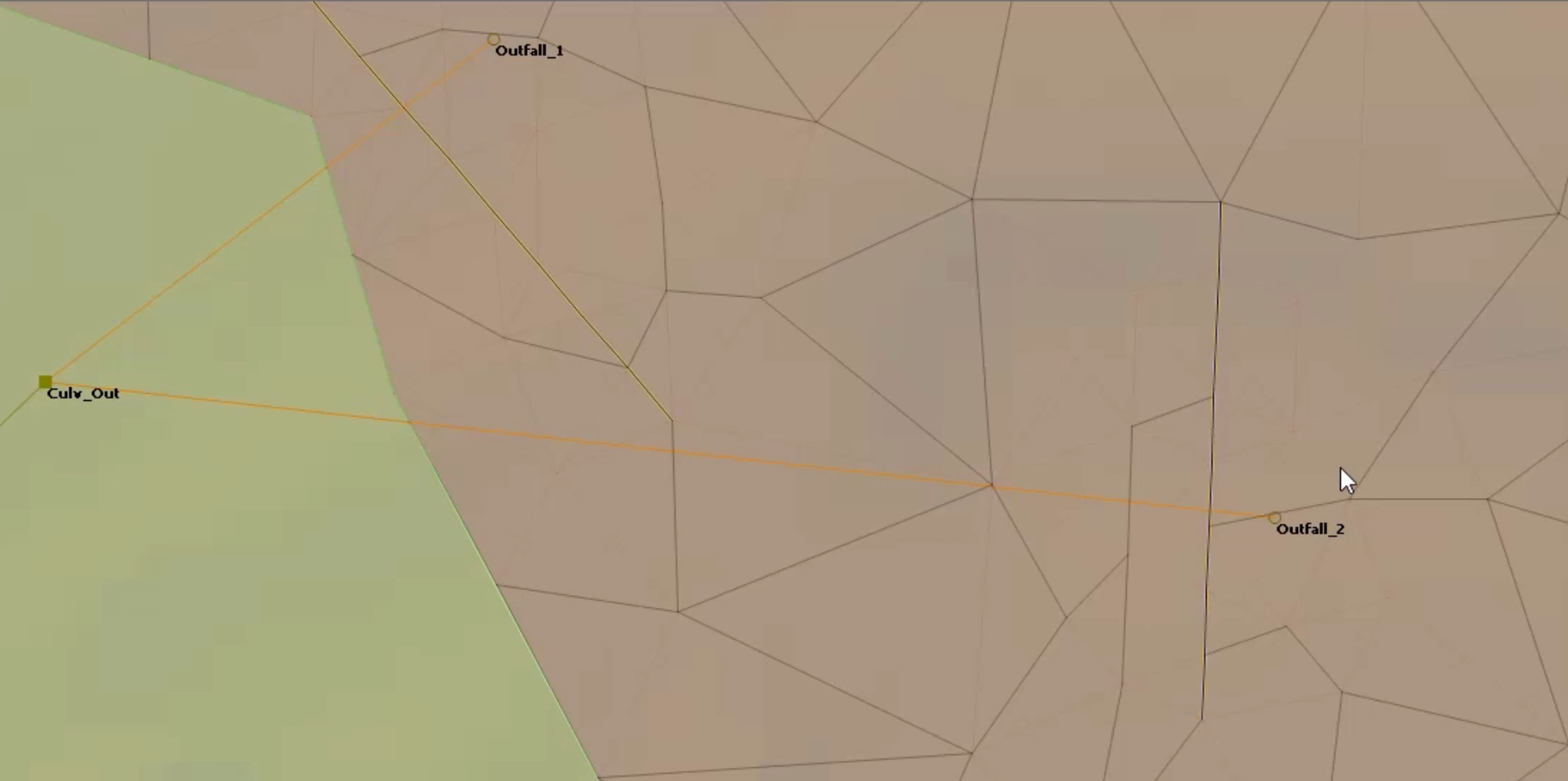
This demonstrates how adding features can increase mesh generation time. This can also lead to the generation of small elements or elements containing many triangles, especially with the classic methodology.
- Click Validate to make sure there are no errors in the network.
- In the Network Validation dialog box, click OK.
- Click Commit changes to database to save the changes.
- Add a comment, such as "Added inline banks".
- Click OK.


