03-001 Practice - Developing the Analytical Model in Revit : Applying Support Conditions
In this practice you will step through the process of enabling/disabling analytical model for structural foundation elements and defining boundary conditions for analytical model.
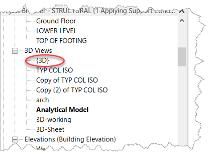
- Open the Small Medical Center-Analytical Supports.rvt project. It opens in the 3D Analytical Model view.
- Open the {3D} view so you can see the physical model.
- Type WT on the keyboard to tile the two views and then type ZA to zoom the views so they fit the windows.
- Right click on the ViewCube and select Orient to a direction> Northeast Isometric in each of the views.
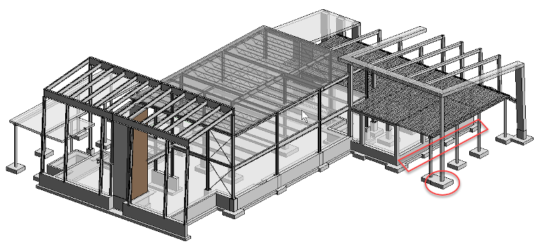
- In the model view, select the foundation pier and strip foundation marked below.
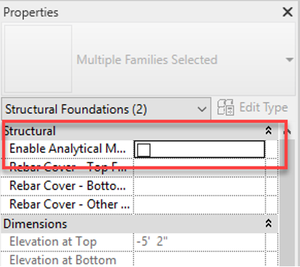
- In Properties, clear the check from Enable Analytical Model, as shown below. In this case we want to specify boundary conditions separately from the model to give better control and bidirectional compatibility when the model is exported to Robot for structural analysis.
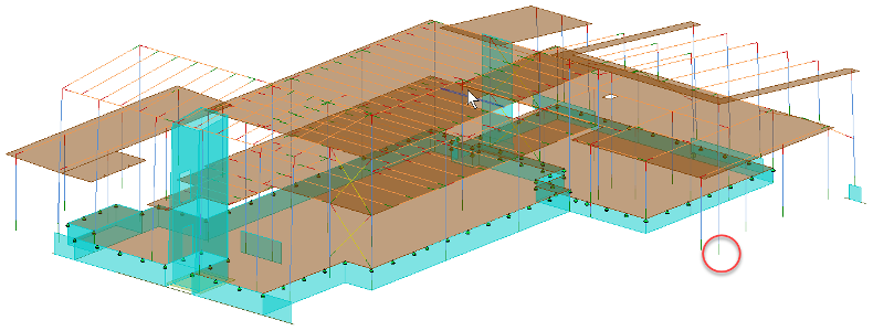
- Click in the Analytical Model view. You will see no difference in visibility in the analytical model whether the analytical model is enabled or not. Zoom in on the column shown below.
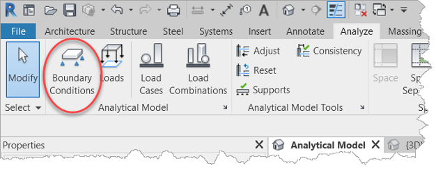
- We now want to specify a boundary condition for this column. In the Analyze tab> Analytical Model panel click Boundary Conditions.
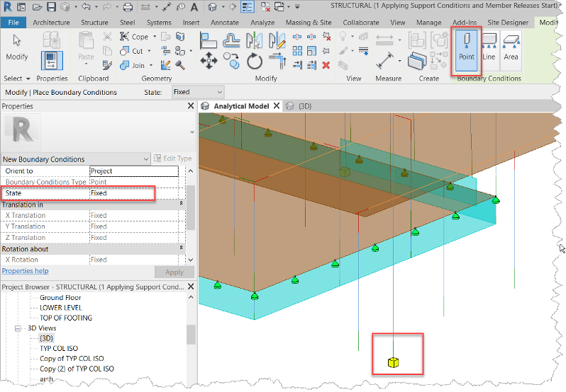
- In the Modify | Place Boundary Conditions tab click Point. Point boundary conditions are used on the ends and joins of structural framing elements such as columns.
- In the Options Bar verify that the State is set to Fixed.
- Click on the bottom of the column as shown below. Add other boundary conditions to the nearby columns if desired.
12. In the Ribbon, change the Boundary to Line. In the Options Bar or Properties set the state to Pinned and select the wall.
13. Click Modify to end the command. You can see the difference between the two icons for Fixed and Pinnned conditions.
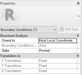
14. Select the nearby boundary condition, as shown below. Notice that is an Area boundary and its state is set to Pinned it is connected to the structural floor.

15. Add boundary conditions to the model so you can better control the bidirectional compatibility when the model is exported to Robot for structural analysis.


