In this lesson, we will develop a Girder component for import as a generic component for InfraWorks.
1. Open Generic Component Sketches.ipt file.
2. Open the Parameters dialog.
3. Change the Equation of SegmentLength to 4m.
4. Update the parameters and click Done.
5. Create a Loft using the Front Sketch and Back Sketch.
6. Make the Front and Back sketches visible again.
7. Create a Loft to cut the middle profiles out of the solid.
8. Restore the 8m value for SegmentLength.
9. Add a Fixed Plane Face Draft using the Front UCS2: YZ Plane as the draft plane and selecting the face on the Front of the part to draft.
10. Set the Draft Angle value to: Skew1=3.
11. Add a Fixed Plane Face Draft using the Back UCS1: YZ Plane as the draft plane and selecting the face on the Back of the part to draft.
12. Set the Draft Angle value to: Skew3=-5.
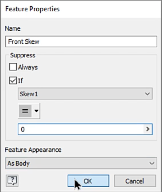
13. Rename the two new Draft features Front Skew and Back Skew based on their position.
14. Right-click on the Front Skew feature and select Properties.
15. Create a Suppression rule that suppresses the feature if the value of the Skew1 parameter is equal to 0.
16. Right-click on the Back Skew feature and select Properties.
17. Create a Suppression rule that suppresses the feature if the value of the Skew2 parameter is equal to 0.
18. Open the Parameters dialog.
19. Edit the values of the Skew1 and Skew2 parameters to have a value of 0.
20. Update the parameters to see the change to the model.
21. Add another Fixed Plane Draft feature using the XZ plane of the Front UCS2 as the fixed plane.
22. Select the Front face of the model and use the existing parameter VerticalSlope1FromPerp to set the draft angle value.
23. Add another Fixed Plane Draft feature using the XZ plane of the Back UCS1 as the fixed plane.
24. Select the Front face of the model and use the existing parameter VerticalSlope2FromPerp to set the draft angle value.
25. Right-click on the FaceDraft3 feature and select Properties.
26. Create a Suppression rule that suppresses the feature if the value of the VerticalSlope1FromPerp parameter is equal to 0.
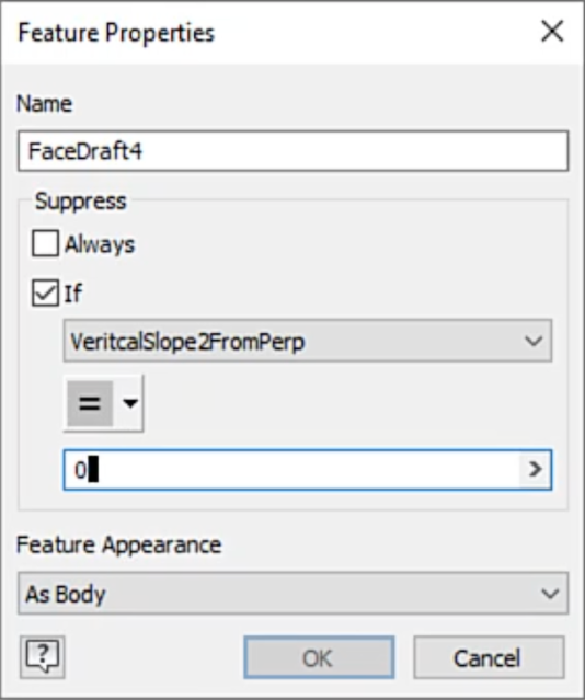
27. Right-click on the FaceDraft4 feature and select Properties.
28. Create a Suppression rule that suppresses the feature if the value of the VerticalSlope2FromPerp parameter is equal to 0.
You can change the names of these features before or after creating the rule and it will not affect the rule.
29. Use the Parameters dialog to change the values of the VerticalSlope1FromPerp and the VerticaSlope2FromPerp parameters to 0 and update the model.
This will effectively suppress all of the draft features in the model.
30. Turn of the visibility of the Back UCS1 and Front UCS2 features in the browser.
31. Switch to the Environments tab and start the Infrastructure Parts Shape Utilities environment.
32. Select Export Template from the toolbar.
33. Set a path for your export and give the target file a name.
34. Click Export to create the file and switch the editor to that file.
35. Select Finish Infrastructure to return to the 3D Model.


