Add structural elements in Advance Steel
Add structural elements - Exercise
Task 1: Start the model and configuring the Advance Steel options
- Open the Medical-Center.dwg file.
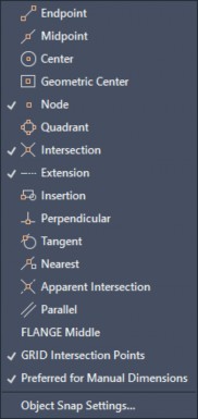
- Select the following Object Snap options.
- Make sure you select the Object Snap Tracking and Polar Tracking options from the status bar, as shown below.
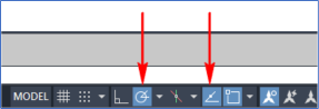
- Set the Polar Tracking to 90, 180, 270, 360 angles.
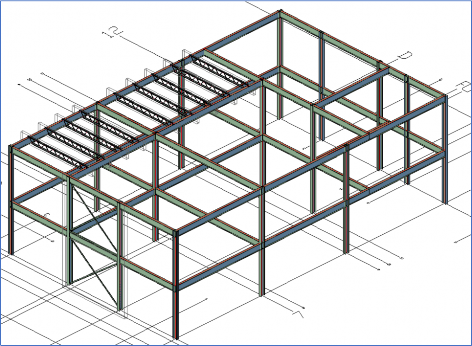
- Navigate to the view shown below.
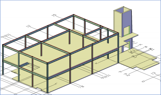
- Select one of the concrete slabs and then select one of the concrete walls.
- Right-click in the blank area and click Select Similar from the shortcut menu. All concrete elements are selected.
- From the Advance Steel Tool Palette > Quick Views category, click the Selected objects off button, as shown below. The concrete elements are turned off.

Task 2: Insert vertical bracings
- Navigate close to the F5 grid intersection point.
- From the Advance Steel Tool Palette > UCS category, click the UCS 3 points tool, as shown below.

- Select the F5 grid intersection point as the origin point of the UCS.
- To specify the point on positive X-direction, move the cursor to the right to snap 270-degrees angle, and click anywhere.
- To specify the point on the positive Y-direction, move the cursor vertically up to track +Z direction, and then click anywhere.
- From the Home ribbon tab > Extending Modeling ribbon panel, click the Bracing tool. You are prompted to select the first point of the bracing.
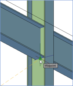
- Using the SHIFT + right mouse click option, invoke the Midpoint object snap, and select the midpoint of the front face of the column as the first point of the bracing, as shown below.

- Using the SHIFT + right mouse click option, invoke the Midpoint object snap, and select the midpoint of the face of the column, shown in the figure below, as the second point of the bracing.
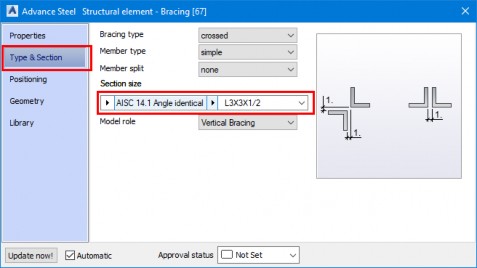
On doing so, the default bracing is created and the Advance Steel Structural element – Bracing dialog box is displayed.
- In the dialog box, invoke the Type & Section tab and set the parameters highlighted in the figure below.
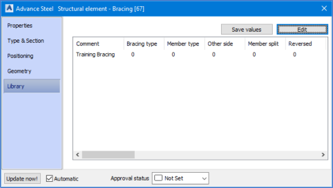
- Click on the Library tab of the dialog box.
- From the top right, click Save values. A new row is added.
- Click the Edit button from the top right. The Library dialog box is displayed.
- Click in the Comment field and enter Training Bracing as the name.
- Click OK in the dialog box. The custom bracing is saved in the dialog box, as shown below.
- Close the dialog box.
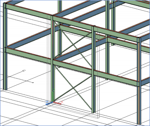
- Similarly, place the bracing on the level above. Use the bracing saved in the Library tab. The following figure shows the bracings created at the two levels.
- Change the UCS to the World UCS by clicking on the first button in the Advance Steel Tool Palette > UCS category.
- Save the model.
Task 3: Change the display type of the structural sections
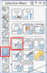
- From the Advance Steel Tool Palette > Selection filters category, click the Beam button, as shown below. All the structural sections are selected.

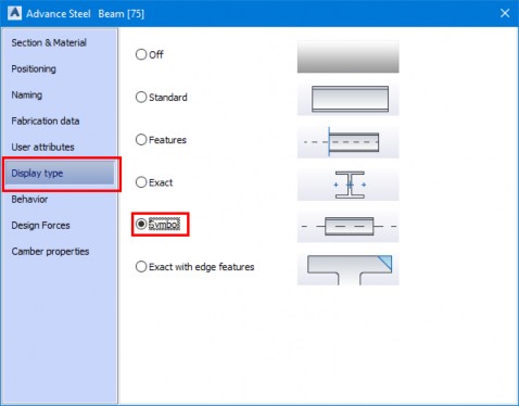
- Right-click in the blank area of the graphics window and select Advance Properties from the shortcut menu. The Advance Steel Beam dialog box is displayed.
- Click the Display Type tab and select Symbol, as shown below. All the steel sections are displayed as system axes.
- Close the dialog box.
Task 4: Insert joists
- From the Home ribbon tab > Extending Modeling ribbon panel, invoke the Joist tool. You are prompted to specify the first point of the joist.
- Using the Object Snap Tracking, track right from the top left point of the model and enter 5', as shown below. The first point of the joist is specified and you are prompted to select the endpoint of the joist.

- Using Polar Tracking, track 270-degrees and snap to the intersection point of the beam on the other side, as shown below. The second point is specified and you are prompted to select the point to define the height of the joist.
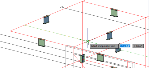
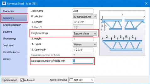
- Move the cursor vertically down to track -Z direction and then enter 1' as the height of the joist. The default joist is added and the Advance Steel Joist dialog box is displayed.
- Activate the Geometry tab and configure the settings as shown below.
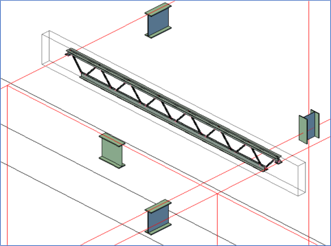
- Add this joist to the library.
- Similarly, create another joist by tracking to the right from the column at the D7 grid intersection point. Use the joist save in the library to create it, as shown below.
- Using the COPY command, select the connection box of the first joist and create 4 copies along the beam with the spacing of 5'.
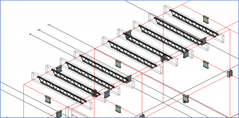
- Similarly, create 5 copies of the second joist with the spacing of 5'6. The model, after creating and copying the joists, as shown below.
Task 5: Restore the standard display of the steel sections
- From the Advance Steel Tool Palette > Selection filters category, click the Beam button, as shown below. All the structural sections are selected.
- Activate the Quick views category of the Advance Steel Tool Palette and click the Standard Presentation button, as shown below.

- Press the ESC key to deselect all the selected sections.
- Zoom to the extents of the model, as shown below, and then save it.