Surface size limitations and simplification - Exercise
Task 1: Attach Point Cloud
- Open drawing named Surface Simplification.dwg, found in the course dataset.
- Select Attach in the Point Cloud group on the Insert Ribbon Tab.
- Browse to and select Intersection and Parking From IW Processing.rcs. Make sure *.rcs is the file type.
- Click on Show Details on the Attach Point Cloud dialog box.
- Verify the number of points in the Point Cloud Data and see that the Classification is Yes.
- Review the attach settings to match the image below.
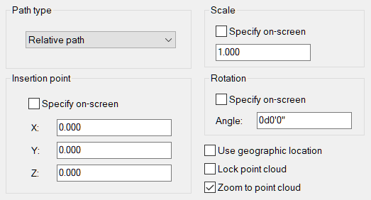
- Select OK.
Task 2: Create TIN surface from Point Cloud
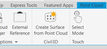
- Select the point cloud by hovering near the edge of the visible data.
- On the Point Cloud context ribbon, select Create Surface from Point Cloud.
- Name the Surface and optionally add a description.
- Change the Style to Contours .5m and 2.5m (Background).
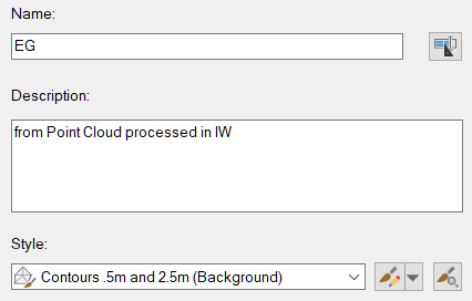
- Click Next.
- Change the Distance Between Points to 0.100. This is the same resolution that was used in the decimation settings when the point cloud was exported after processing in Recap.
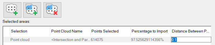
- Note that the number of point selected is slightly less than the number of points in the original point cloud data.
- Click Next.
- Toggle on No filter method.
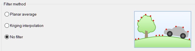
- Select Create Surface.
- Note the alert that indicates the processing is happing in the background and it is OK to continue working.
- Close the Alert box.
- After a few moments the surface is created. Review the Events viewer to see that some points were not included as they were duplicates. Dismiss the Events Viewer.
Task 3: Change display to view surface better
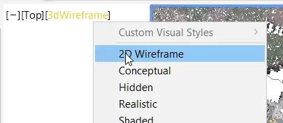
- Change the View Style in the upper left corner of the drawing canvas to 2D Wireframe.
Task 4: Change the layer of the Point Cloud
To easily control the visibility of the point cloud, it will be placed on its own unique layer.
- Change to the Home Ribbon.
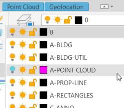
- Select the Point Cloud by the text or frame.
- Change the Layer to A-POINT CLOUD.
- Close the alert box indicating the Objects Moved to Frozen or Turned Off Layers.
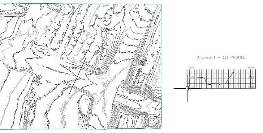
Task 5: Create quick profile
A quick profile is used to quickly look at a section across the roadway. A named viewport will be used to split the view between the plan view and the quick profile view so that the profile view can be manipulated using grips on the defining line.
- Zoom into an area near the main intersection and draw a line entity to represent a section view.
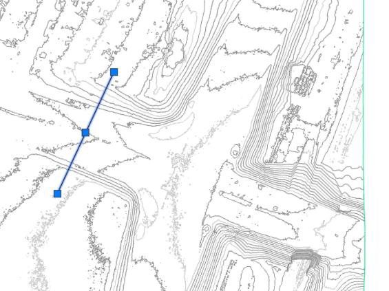
- Select the line entity and click on Quick Profile on the right-click pop-up menu.
- Accept the defaults in the Create Quick Profiles dialog box.
- Place the profile view to the right of the main intersection.
- Dismiss the Event Viewer.
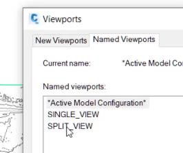
- On the View Tab of the ribbon, select Named in the Model Viewports group.
- In the Viewports dialog box, select SPLIT_VIEW.
- Use pan and zoom to arrange the views in the viewports so that the line and contour map is in the left viewport and the quick profile is in the right viewport.
Task 6: Edit surface style to show triangulation
- Showing the triangulation of the surface data will show how much we are able to simplify the data.
- Select on the contour map in the left viewport to highlight the surface object.
- On the right-click pop-up menu, select Edit Surface Style.
- On the Display tab of the Surface Style dialog box, click on the lightbulb icon next to the Triangles component to turn it on.
- Click OK to close the dialog box and see that the TIN triangles are now showing in an orange color.
Task 7: Simplify the surface
Using surface simplification methods, the surface contour map and section view will improve to better represent a roadway with side slopes condition.
- Select on the contour map in the left viewport to highlight the surface object.
- In the context ribbon, select on Edit Surface in the Modify group and click on Simplify Surface.
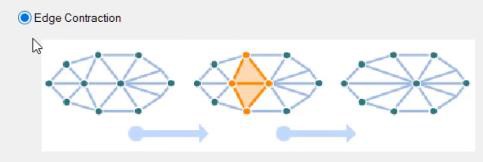
- Select Edge Contraction as the Simplify Method.
- Click Next.
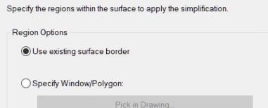
- Select Use existing surface border in the Region Options.
- Click Next.
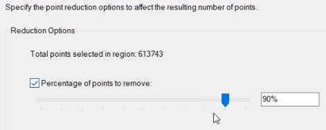
- In the Reduction Options, make a note of the number of points in the region.
- Use the slider or edit box to enter 90% as the percentage of point to remove.
- Click Finish.
- Note the reduction in the density of the TIN triangles, and where the density was most affected. Also note the Quick Profile view and it is smoothing out to a better representation of a travel way.
Task 9: Repeat simplify surface
Performing an additional Surface Simplification will further reduce the number of points and the TIN density of the surface.
Repeat the procedure in Task 8 – note that the number of points is now about 61375. Use the same 90% reduction value and click on Finish.
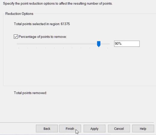
This simplification gives a TIN surface that displays contours and a Quick Profile section that represents a roadway separated by a median with side slopes and sidewalks on the northern side.
The original surface had over 600 thousand points and after two simplification steps using Edge Contraction at 90% the resulting surface has just over 6 thousand points. This results in a very efficient surface with the number of points much lower than the maximum number of 1.5 million points.
You do not need to save this Civil 3D drawing.


