Performing steel design in Robot - Exercise
In this practice, you will step through the process of verifying in Robot some members according to the steel design code ANSI/AISC 360-16, defining design group and performing code group design with active weight optimization.
- Open Autodesk Robot Structural Analysis Professional 2020.
- Open in it the project STRUCTURAL_before design_res.rtd.
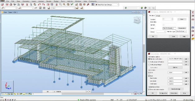
- Select the Steel Design > Steel/Aluminum Design layout, as marked below.

- This screen layout is composed of a graphic view on the left side, the dialog-box with the Definitions of members and design groups in the right-top corner of the screen, and the dialog box of Calculations according to active steel design code in the right-bottom corner of the screen.
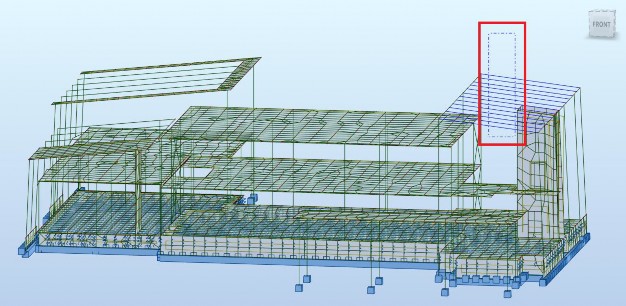
- Rotate the model to be able to perform selection of bars on the right side, as shown below. Drag the mouse cursor from right to left to select bars even partially contained in the selection rectangle.
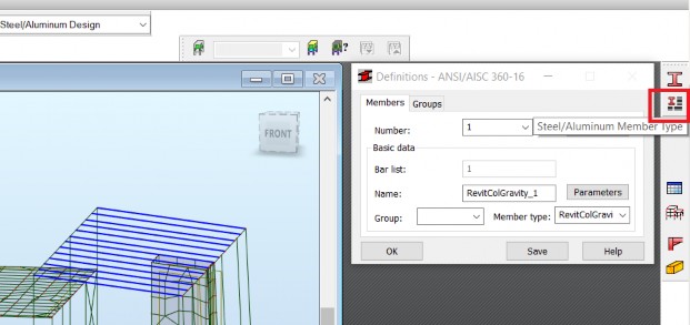
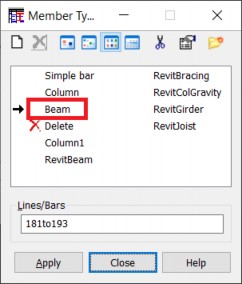
- Click the Steel/Aluminum Member Type icon from the right-side vertical toolbar. It results in displaying the Member Type dialog box. Double-click the Beam type.
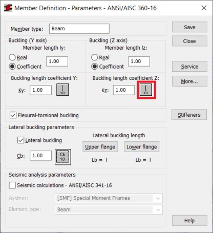
- The Member Definition Parameters – ANSI/AISC 360-16 dialog box is open. Select the icon of buckling conditions about the weak axis Z.
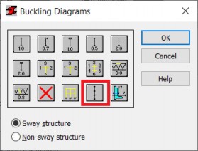
- The Buckling Diagrams dialog box is open. Select the icon corresponding to the intermediate bracings.
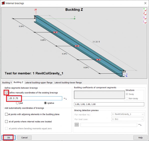
- The Internal bracings dialog box is open. Activate Define manually coordinates of the existing bracings and input relative positions .25 .5 .75 (corresponding to 25%, 50% and 75% of member length). Select OK to accept and close this dialog box.
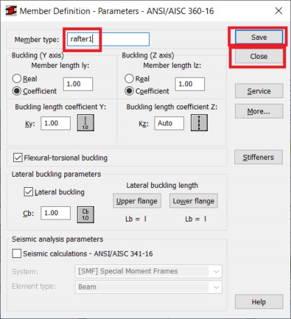
- Change the name of the Member type to rafter1, select Save, and Close.
- It can be noticed in the Member Type dialog box that the new type rafter1 was added, it is active, and that the selection of bars made before (181to193) was automatically transferred to the Lines/Bars field of the dialog box. Select Apply to assign this type to selected bars.
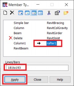
- Select Close to close the dialog box.
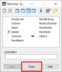
- Click the marked field next to Member verification and then select again the bars as in point 5. above.
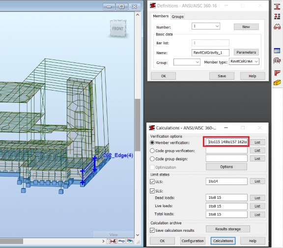
- Bars are selected again and the selection is automatically transferred to the field next to Member verification.
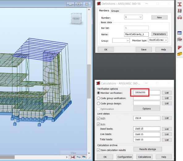
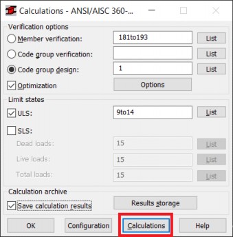
- Define the lists of combinations for calculations: 9to14 for ULS and 15 for SLS. Select Calculations to perform Member verification for the selected list of bars.
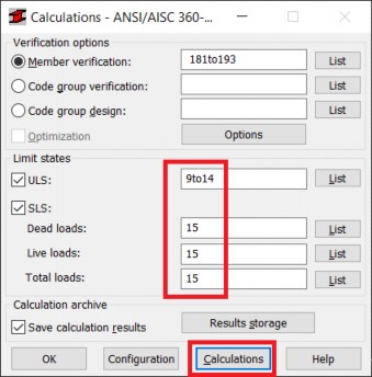
- The short summary of verification is displayed. It can be noticed that the efficiency ratio for all verified bars is about 0.5. Click the line of this table corresponding to specific member to display more detailed results for it.

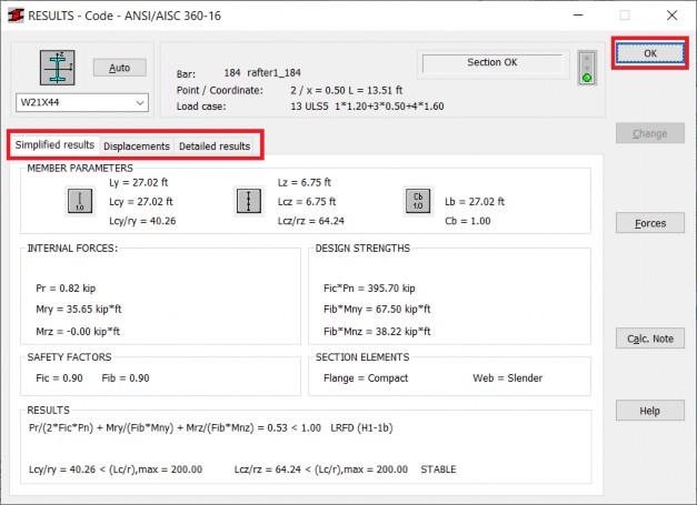
- The RESULTS window is displayed. Switch between the Simplified results, Displacements and Detailed results tabs to see available information concerning design forces and moments, design code parameters and formulas, and code references. Select OK to close the window.
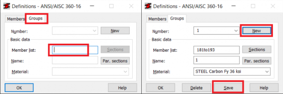
- Switch to the Groups tab of the Definitions dialog box and click the Member list field. The current bar selection list 181to193 should automatically transfer there. Select New to create a new design group for the current member list. Select Save to save the created group.
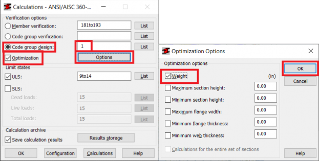
- Select Code group design in the Calculations dialog box, input the list of groups 1, activate Optimization, and select Options. The Optimization Options dialog box is open. Activate Weight in it and select OK to accept and close.
- Select Calculations to perform code group design with the optimization of weight.
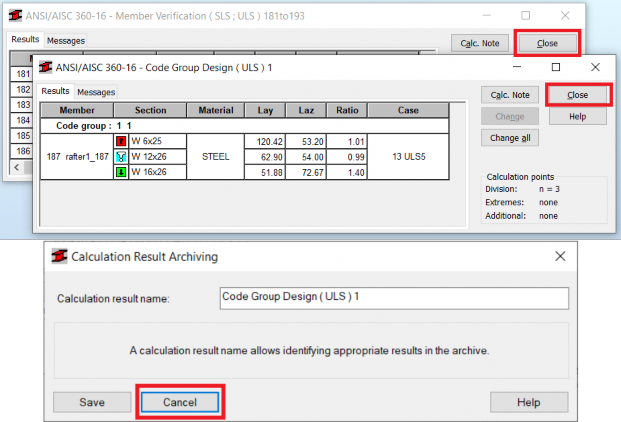
- The short summary of group design is displayed. As the group was defined without creating the list of sections to be used in optimization and the original section in members of optimized group was W 21x44 Robot searches for the optimum replacement between all W sections. The optimum section is marked with the blue exclamation sign. It can be noticed that the optimum section found is W 12x26 while the original section in these bars is W 21x44. The efficiency ratio for the optimum section increased from about 0.5 to 0.99.

- The above dialog box contains a Change all button. Using it results in replacing the original section in the model with the optimum one. After using it the status of results changes from available to out of date, so re-calculation of static analysis is necessary. The change of section results in changes of distribution of forces and moments so the Code group verification should be performed to justify the modification made.
- Select Close in windows corresponding to results of Code Group Design and Member Verification. When closing these windows, the Calculation Results Archiving dialog box is displayed. Select Cancel in it, to not save the results of steel design inside the model.
- Save the model with a new name using File > Save As… from the pull-down text menu.
 AutoCAD
 AutoCAD LT
 Fusion
 AutoCAD Revit LT Suite
 Architecture, Engineering & Construction Collection
 Revit
Revit Civil 3D
 BIM Collaborate Pro
 Product Design & Manufacturing Collection
 Maya
Maya Inventor
 Navisworks
 3DS Max
 Fusion Extensions
 Revit LT
 Forma
Forma Recap Pro
 Alias Concept
 Maya Creative
 Flame
Flame Arnold
 Mudbox
 Flow Capture
 Media & Entertainment Collection


