Insert standard components

Insert standard components - Exercise

Task 1: Insert a bolted connection

  1. From the project files, open Belt Driven Gear Reducer 4.dwg
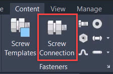
  2. In the Content tab>Fasteners panel, click Screw Connection.


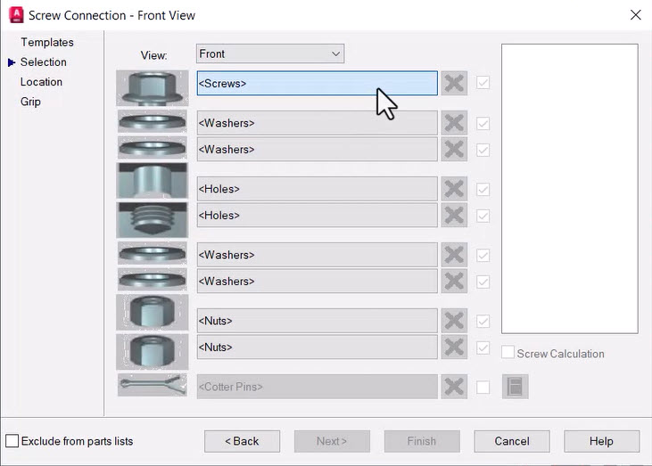
  3. In the Screw Connection - Front View dialog box, click <Screws>.


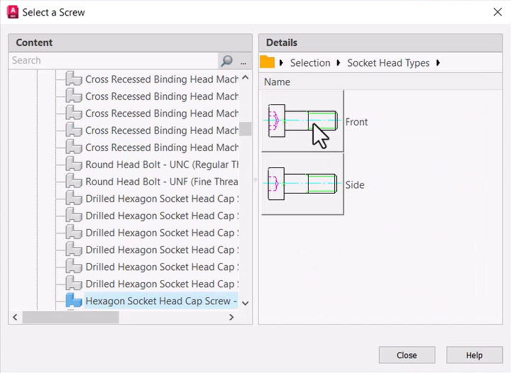
  4. In the Select a Screw dialog box, select Socket Head Types>Hexagon Socket Head Cap Screw – UNC (Regular Thread - Inch)>Front.


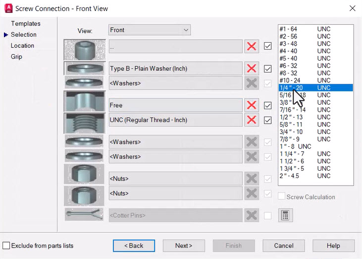
  5. In the Screw Connection - Front View dialog box, click <Washers>
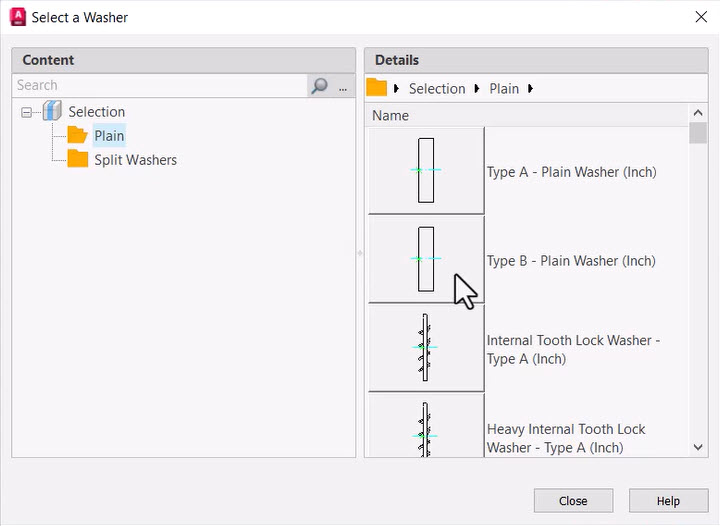
  6. In the Select a Washer dialog box, select Plain>Type B - Plain Washer (Inch).


  7. In the Screw Connection - Front View dialog box, click the first <Holes> in the list. 
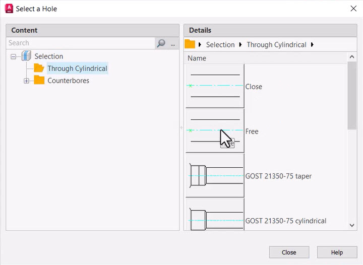
  8. In the Select a Hole dialog box, select Through Cylindrical>Free.


  9. In the Screw Connection - Front View dialog box, click the second <Holes> in the list. 
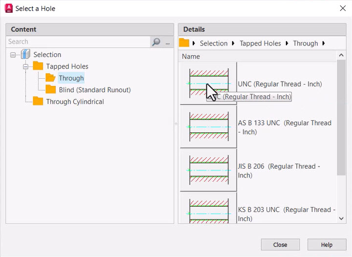
  10. In the Select a Hole dialog box, select Tapped Holes>Through>UNC (Regular Thread - Inch).


  11. Select 1/4″ - 20 UNC from the list on the right-hand side of the Screw Connection dialog box and click Next.


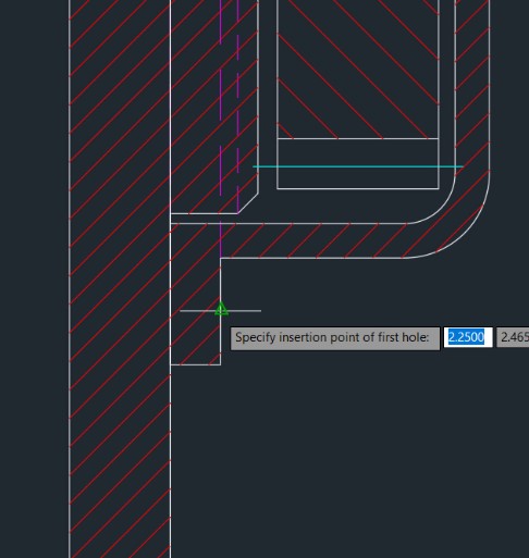
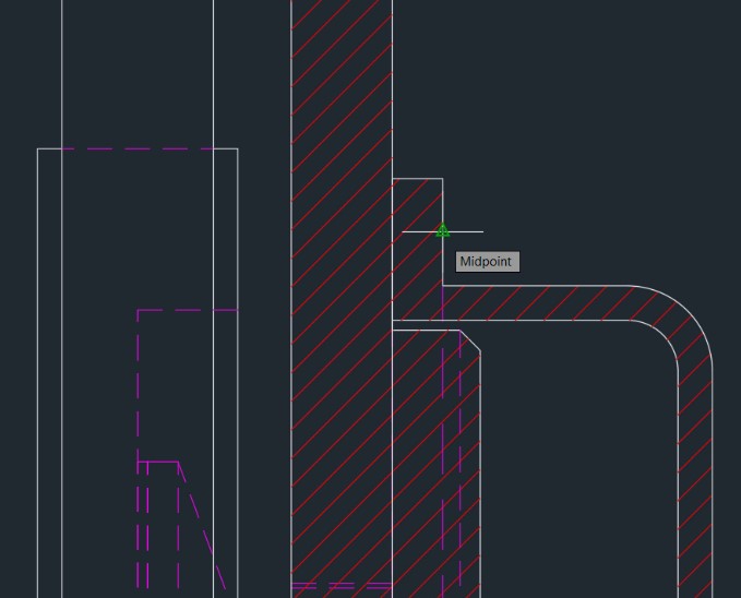
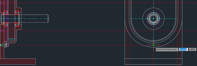
  12. At the Specify insertion point of first hole prompt, select the midpoint of the right short vertical line at the bottom of GEAR COVER:1, as shown below.


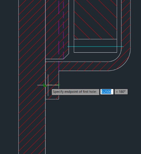
  13. At the Specify endpoint of first hole prompt, select a point straight to the left of the first point selected and on the left short vertical line at the bottom of GEAR COVER:1, so that the directional line of the first hole is perpendicular to the left short vertical line at the bottom of GEAR COVER:1, as shown below.


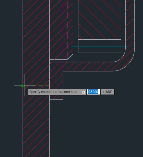
  14. At the Specify endpoint of second hole prompt, select a point straight to the left of the last point selected and on the left vertical line at the bottom of STAND:1, so that the directional line of the second hole is perpendicular to the left vertical line at the bottom of STAND:1, as shown below.


  15. In the Screw Assembly Location - Front View dialog box, confirm the Insertion Point coordinates and click Next
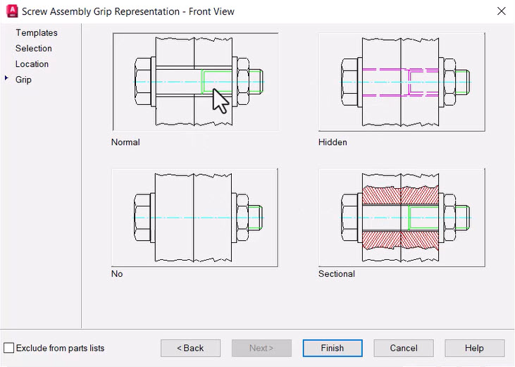
  16. In the Screw Assembly Grip Representation - Front View dialog box, select Normal and click Finish.


  17. In the Select Part Size dialog box, select ANSI B18.22.1 - 1/4 - narrow - Type B and click OK
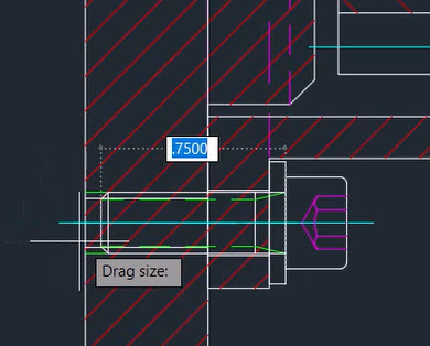
  18. Drag the part so it fits in the drawing, clicking when the length value is .75, as shown below.


  19. In the Home tab>Modify panel, click Copy
  20. Select the bolted connection SCREW CON1:1 that was just inserted in the drawing. 
  21. At the Specify insertion point prompt, select the midpoint of the right short vertical line at the top of GEAR COVER:1, as shown below.


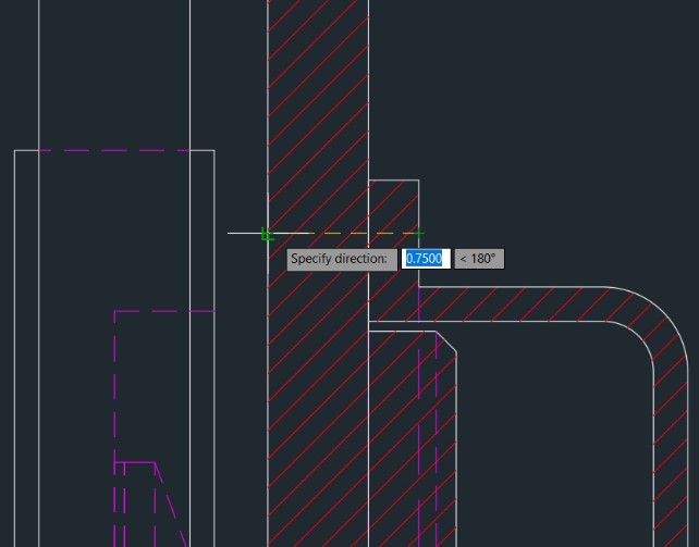
  22. At the Specify direction prompt, select a point directly to the left of the previous point selected, as shown below.


  23. To add construction lines, in the Home tab>Construction panel, click Construction Lines.  
  24. In the Construction Lines dialog box, click the Horizontal construction line option. At the Specify insertion point prompts, click the right endpoint of each of the centerlines of the last two bolted connections that were just placed, as shown below, then press <Esc> to end and exit the command.


  25. In the Content tab>Tools panel, click Power View.


  26. Select the bottom bolted connection. 
  27. In the dialog box prompting which view should be drawn, click Top
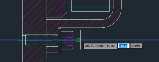
  28. To place the power view in the drawing, at the Specify insertion point prompt, select the intersection of the two construction lines, as shown below.


  29. In the Home tab>Modify panel, click Copy
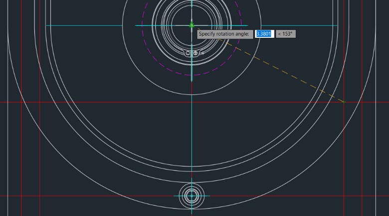
  30. Select the Front view of the bolted connection that was just placed with the Power View command, then place two more front view instances of the copied bolted connection in the drawing using the intersections of the construction lines for their insertion points, and the intersection of the two blue centerlines when specifying the rotation angles, as shown below.


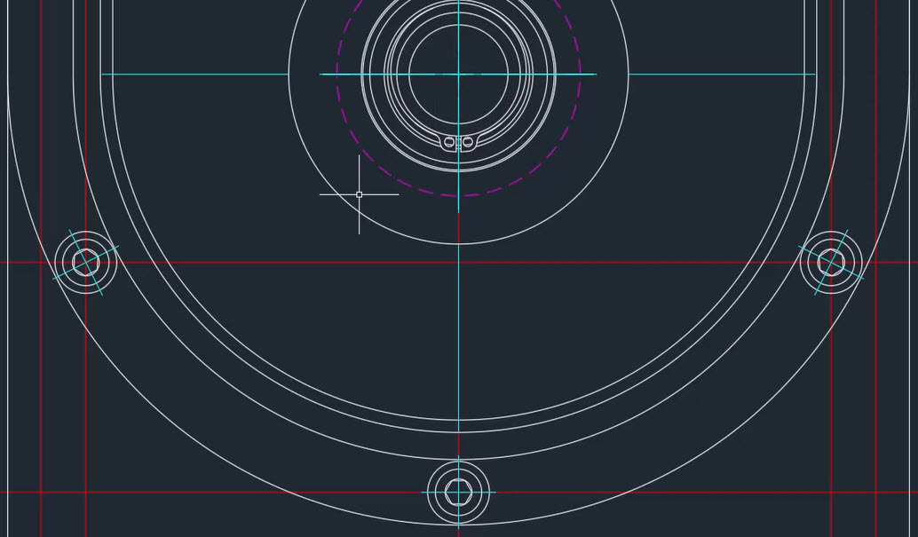
    • Once the two instances are placed, your drawing should appear similar to the one shown below.


Task 2: Insert a spring

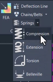
  1. In the Content tab>Calculation panel, click the drop-down arrow beside Springs and select Compression.


  2. In the Select Compression Spring dialog box, select Only Draw>Front
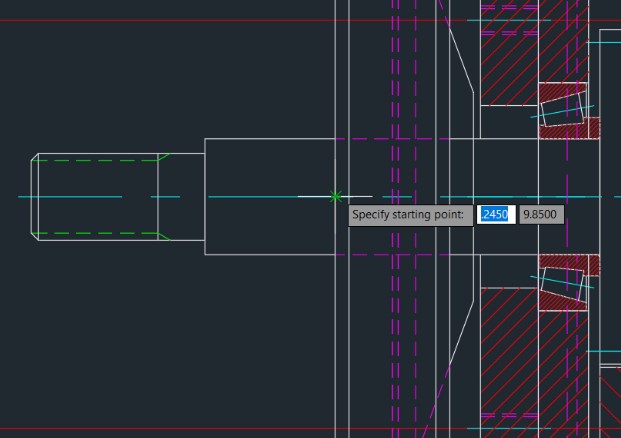
  3. To place the spring in the drawing, at the Specify starting point prompt, select the intersection of the left tall vertical line of SYNCHRONOUS BELT 1:1 and the centerline of INPUT SHAFT:1, as shown below.


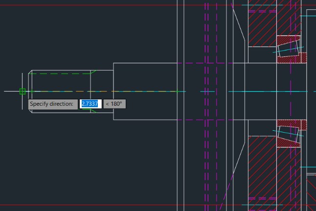
  4. At the Specify direction prompt, click the left endpoint of the centerline of INPUT SHAFT:1, as shown below.


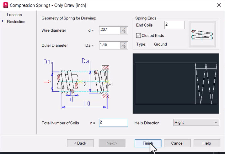
  5. In the Compression Springs - Only Draw [inch] dialog box, set the following: 
    • Wire diameter d = .207
    • Outer Diameter Da = 1.45
    • Total Number of Coils n = 2


  6. Click Finish
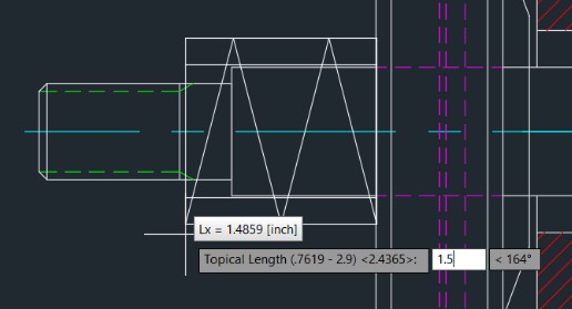
  7. At the Topical Length prompt, drag to vary the size of the spring, then enter a value of 1.5 (as shown below) and press <Enter>.


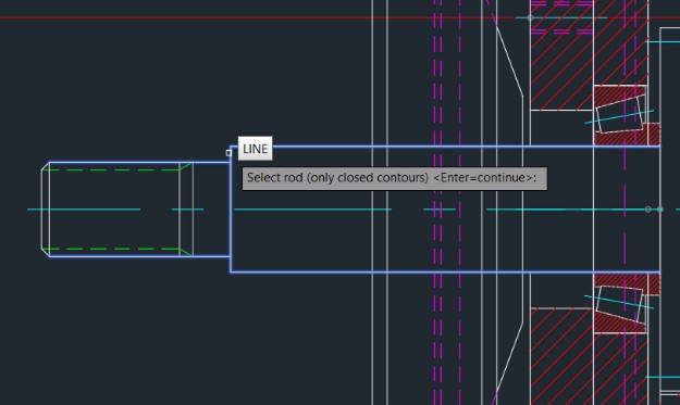
  8. At the Select rod prompt, select the three top and three bottom horizontal lines and the single large vertical line that make up the left half of the INPUT SHAFT:1, as shown below, and then right-click the mouse.


  9. In the Hide Situation dialog box, verify that the Display hidden lines option is unchecked and click OK.

Task 3: Insert a washer

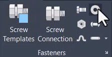
  1. In the Content tab>Fasteners panel, click Washer.


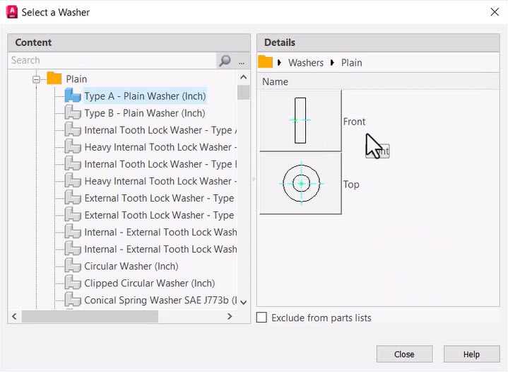
  2. In the Select a Washer dialog box, select Plain>Type A - Plain Washer (Inch)>Front.


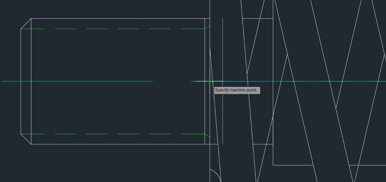
  3. To place the washer in the drawing, at the Specify insertion point prompt, select the intersection of the centerline and the left vertical line of the COMPRESSION SPRING, as shown below.


  4. At the Specify rotation angle prompt, select a point along the centerline to the left of the COMPRESSION SPRING. 
  5. In the Type A - Plain Washer (Inch) - Nominal Diameter dialog box, select 3/4″ and click Finish
  6. In the Select Part Size dialog box, confirm that ANSI B18.22.1 - 3/4 - narrow - Type A is selected and click OK
  7. In the Hide Situation dialog box, verify that the Display hidden lines option is unchecked and click OK.

Task 4: Insert a nut

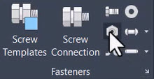
  1. In the Content tab>Fasteners panel, click Nut.


  2. In the Select a Nut dialog box, select Hex Nuts>Hex Jam Nut - UNC (Regular Thread - Inch)>Front
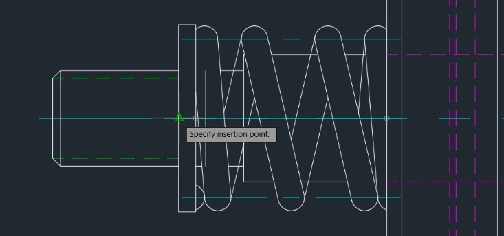
  3. To place the nut in the drawing, at the Specify insertion point prompt, select the intersection of the centerline and the left vertical line of WASHER A 1:2, as shown below.


  4. At the Specify rotation angle prompt, select a point along the centerline and to the left of the WASHER A 1:2. 
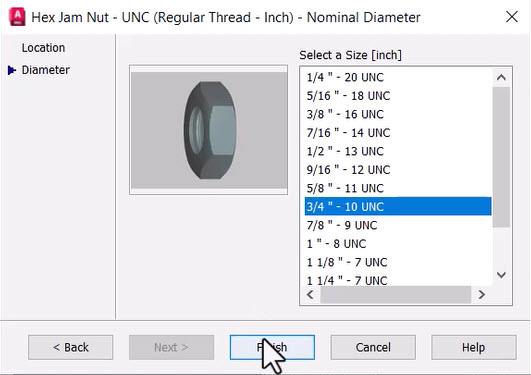
  5. In the Hex Jam Nut - UNC (Regular Thread - Inch) - Nominal Diameter dialog box, select 3/4″ - 10 UNC and click Finish.


  6. In the Hide Situation dialog box, verify that the Display hidden lines option is unchecked, and click OK.  
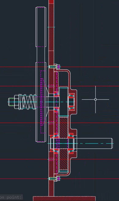
  7. Save the drawing. Your completed drawing should look similar to the one shown below.