• InfoWorks ICM

Inferring missing object data

Use the Inference tool to populate missing values.


Tutorial resources

These downloadable resources will be used to complete this tutorial:

Inf_Msg_Data.zip

Step-by-step guide

When building a 1D urban drainage network, InfoWorks ICM offers several tools to help speed up the process, such as Define Branches and Area Take Off. Some parameters may be missing because a survey was not completed, or because of incorrect user input. To fill in this missing information quickly and easily, you can use the Inference tool to populate missing fields. The Inference tool works out the missing value using approximation rules based on surrounding data.
  1. Open the transportable database .icmt file for this tutorial.
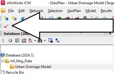
  2. From the toolbar, click Validate to validate the model.

In the InfoWorks ICM toolbar, Validate is highlighted and called out.</p>

  1. In the Network Validation dialog box, click OK.

In the Output window, three red error messages appear to indicate missing values. In the GeoPlan, node TF92291602 and conduit TF92293601.1 are selected, as they have missing data.
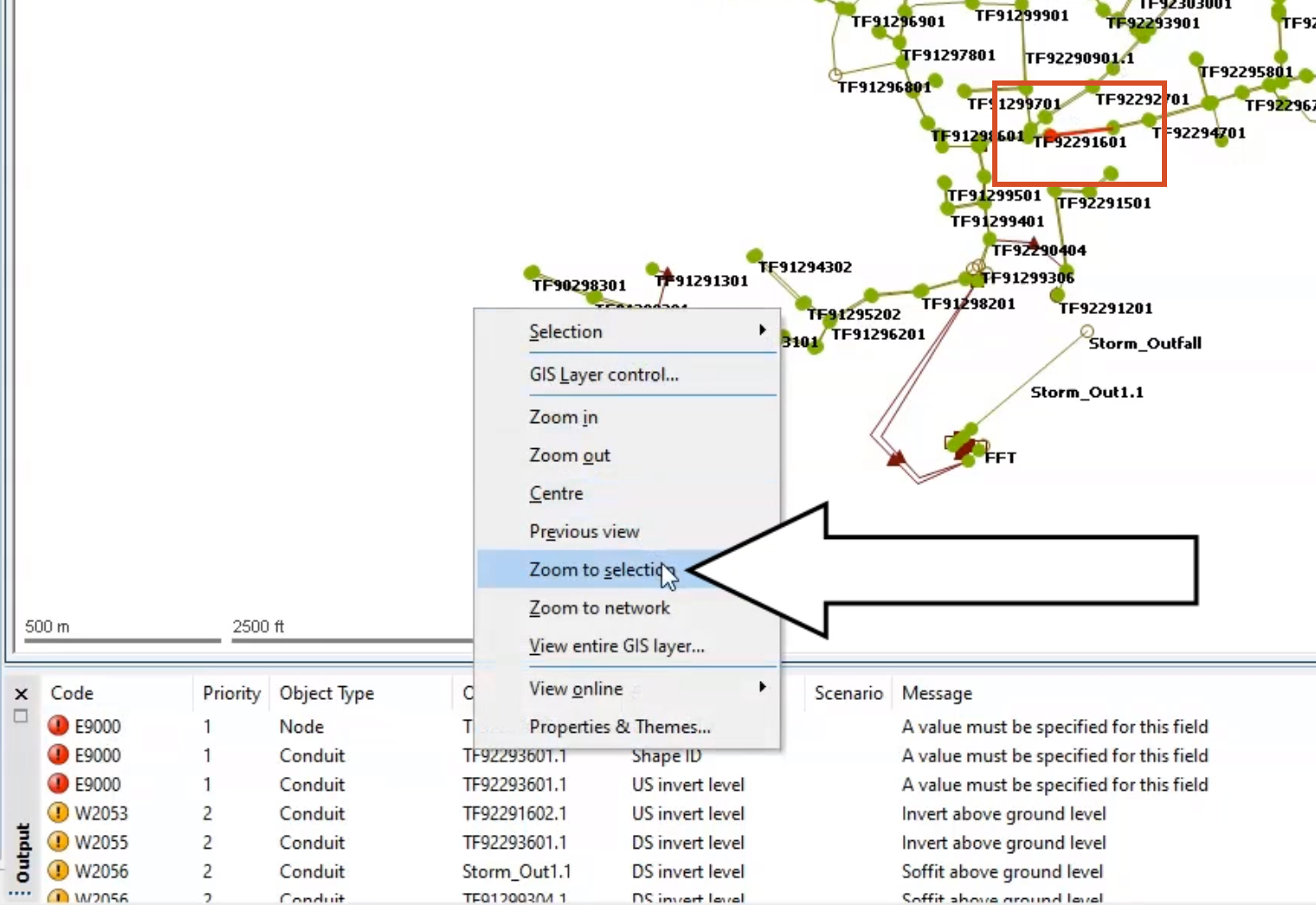
  1. Right click the GeoPlan and select Zoom to selection.

The Output window shows three red error messages, and in the GeoPlan, the selected node and conduit are highlighted in red, and Zoom to selection is selected in the shortcut menu.

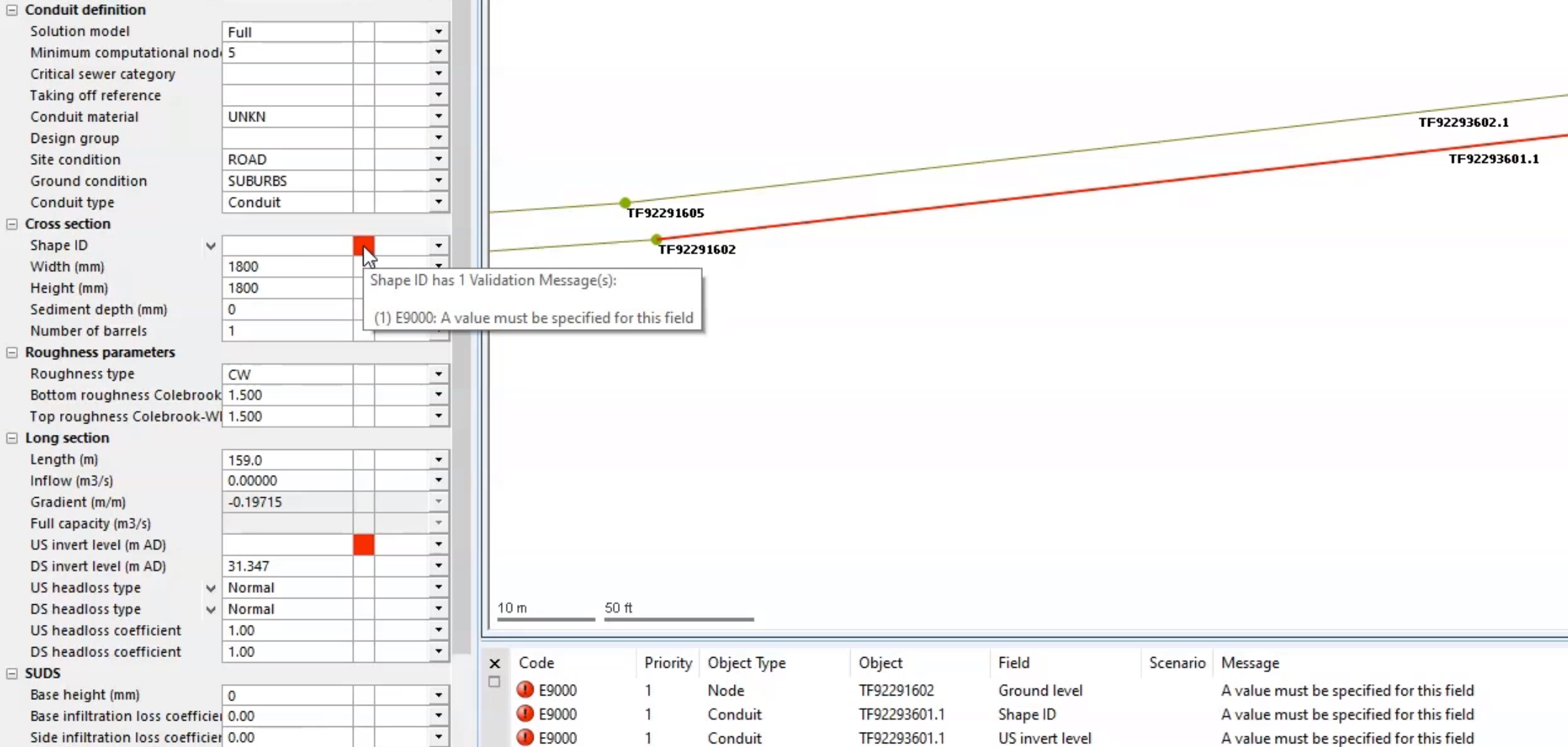
  1. Select each object individually to inspect the missing values in the Properties window.

The Properties window with two red validation errors for the selected object, highlighted in red on the zoomed-in GeoPlan.

  1. From the Edit toolbar, expand the Use edit flag drop-down.
  2. Select IN to use the previously set-up inference flag.

In the Edit toolbar, Use edit flag drop-down, IN is selected.

Now, use the Inference tool to populate the missing values:

  1. At the bottom of the Properties window, click the Database tab.
  2. In the Database, right-click the Model Group and select New InfoWorks > Inference.
  3. In the New Name – Inference dialog box, click OK to accept the default name.

From the Database, right-click the new Inference entry and select Open.
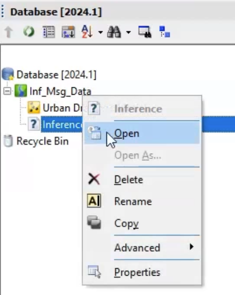
In the Database, the Inference shortcut menu with Open selected.

The Inference Data Editor opens with all rules selected by default.
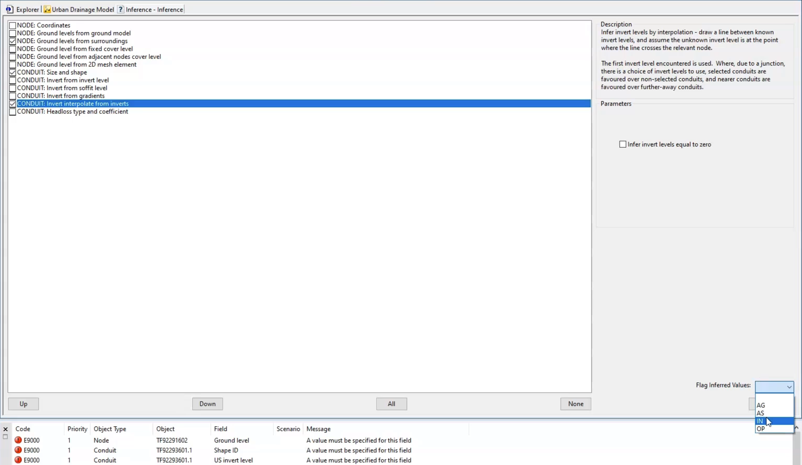
  1. Click None to deselect all the rules.
  2. In the list of rules, select NODE: ground levels from surroundings.
  3. Select CONDUIT: Size and Shape inference (along with the Infer Shape parameter).
  4. Select CONDUIT: Invert interpolate from inverts.
  5. In the Flag Inferred Values drop-down, select the IN flag.

In the Inference list, checkboxes are selected next to three node and conduit rules, and in the Flag Inferred Values drop-down, IN is selected.

  1. Click Save.
  2. Close the Inference window.
  3. In the GeoPlan, ensure that you have both objects selected or no objects selected.
  4. From the Database, drag Inference and drop it into the network GeoPlan to infer the appropriate values.
  5. Re-validate the network.

In the Output window, the previous error messages are removed.

In the Output window, no error messages display.

  1. Check the Properties values in the relevant links and nodes to see that the missing values now appear, with the IN flag set.
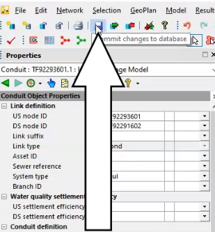
  2. Click Commit to commit the changes to the new network.

In the toolbar, the Commit button is selected.

  1. Add a comment of "Inference tool applied".
  2. Click OK.

Be aware that the inference calculations can take some time on a much larger model, or a model that has more data to calculate than in this example.