Step-by-step guide
Void bodies are defined in the Inventor model, and when they are published to Revit with Informed Design, they become cutting objects. In Revit, these void objects within loadable families can be used to cut into their specified host objects.
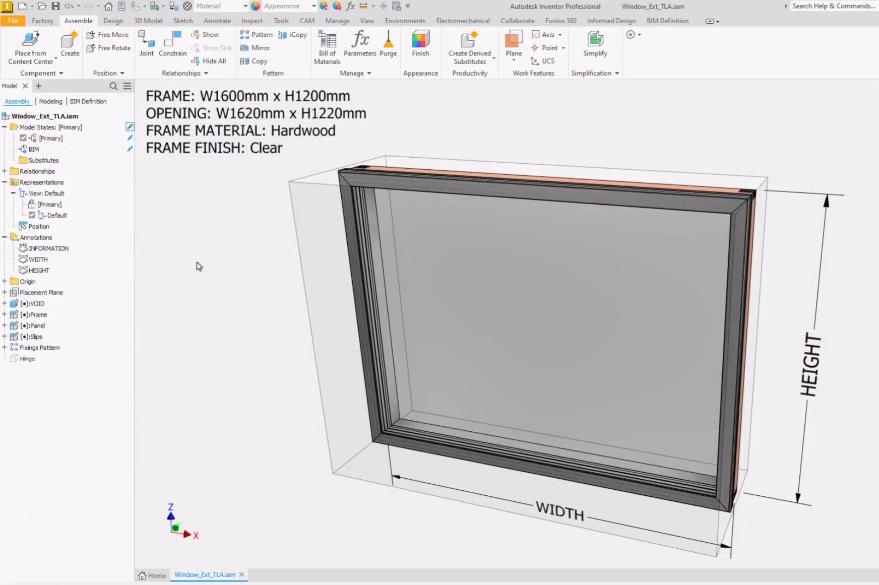
In this example, a component has been added to represent a void object in the Inventor assembly. The void object is the hole that needs to be cut into the host wall for a window.
To begin, in Inventor, complete the BIM properties for the void body.
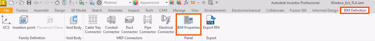
- Navigate to the BIM Definition tab and select BIM Properties.
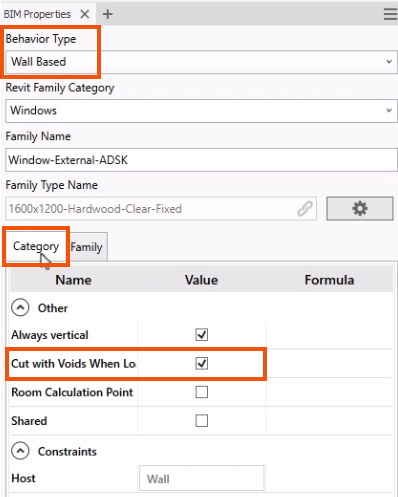
In the BIM Properties panel, note that this family is Wall Based. This means that the Revit family generated from this model can only be placed onto walls in the Revit project.
- Select the Category tab to verify that Cut with Voids When Loaded is selected.
With the BIM Properties complete, next, define the void body.
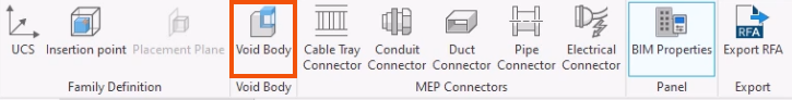
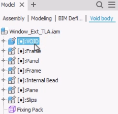
- On the BIM Definition tab, click Void Body.
- In the Void body browser, select the component to define as a void, such as VOID.
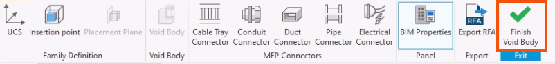
- On the ribbon, click Finish Void Body.
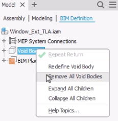
Once they are created, void bodies are found in the BIM Definition browser.
- Right-click the top-level Void Bodies node to redefine a void body or to remove all void bodies.
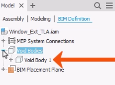
- Expand Void Bodies to view individual void bodies. An individual void body can also be right-clicked for removal.
The void body is now defined and will be included when a Revit family is created by publishing to Informed Design or exporting an RFA.
Once it is published, the family can be placed using the Informed Design add-in for Revit.
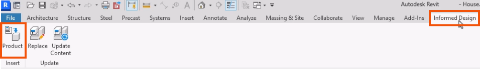
- In Revit, select the Informed Design tab.
- Click Product Insert.
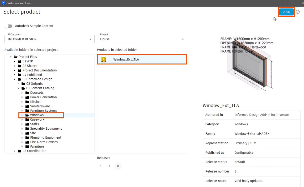
- In the Customize and Insert dialog box, select the void body. For this example, in the Windows folder, select Window_Ext_TLA.
- Click Open.
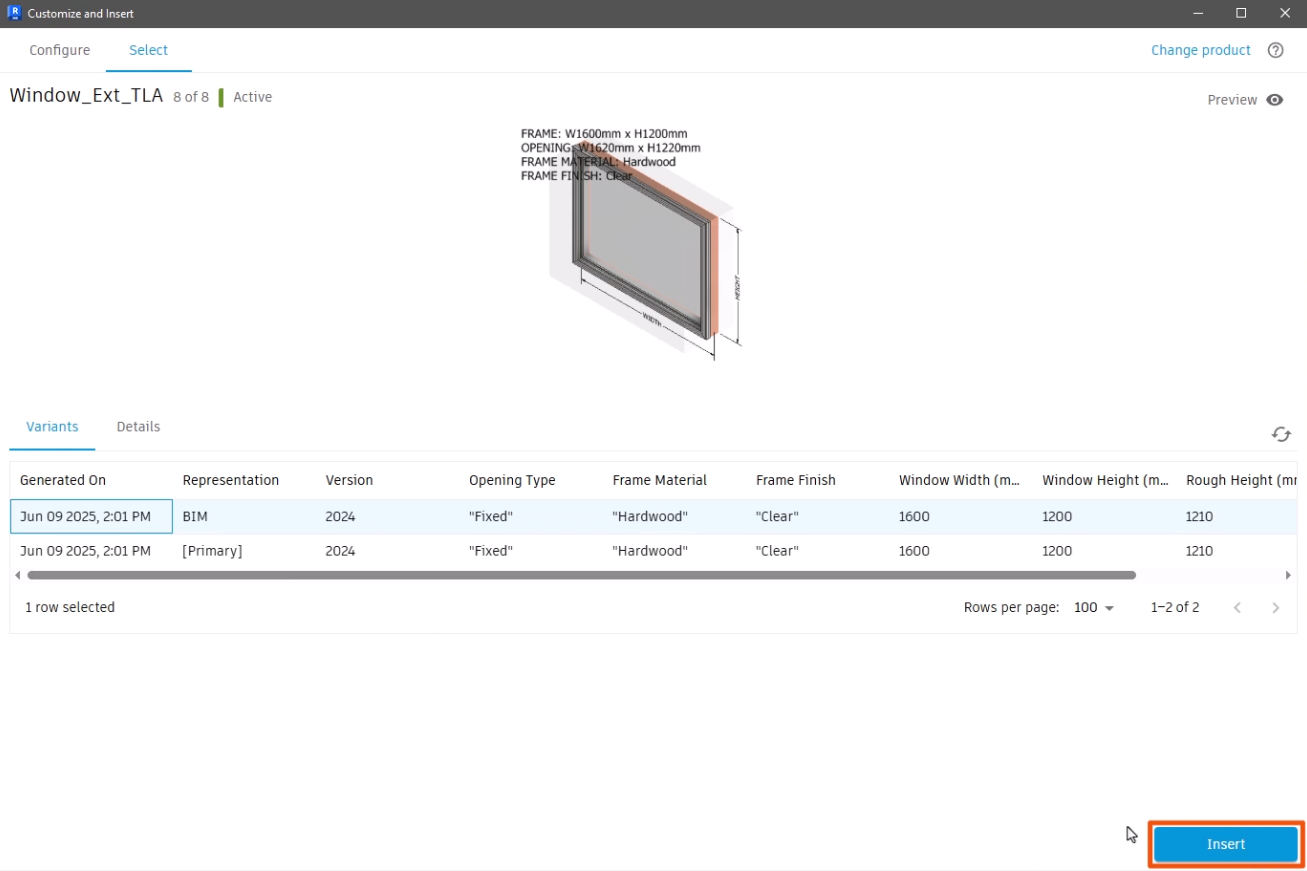
- On the Select tab, choose a representation, such as BIM.
- Click Insert.
- To place the void body in the Revit model, click the desired location on the wall. In this case, a couple of instances are placed.
To cut a void:
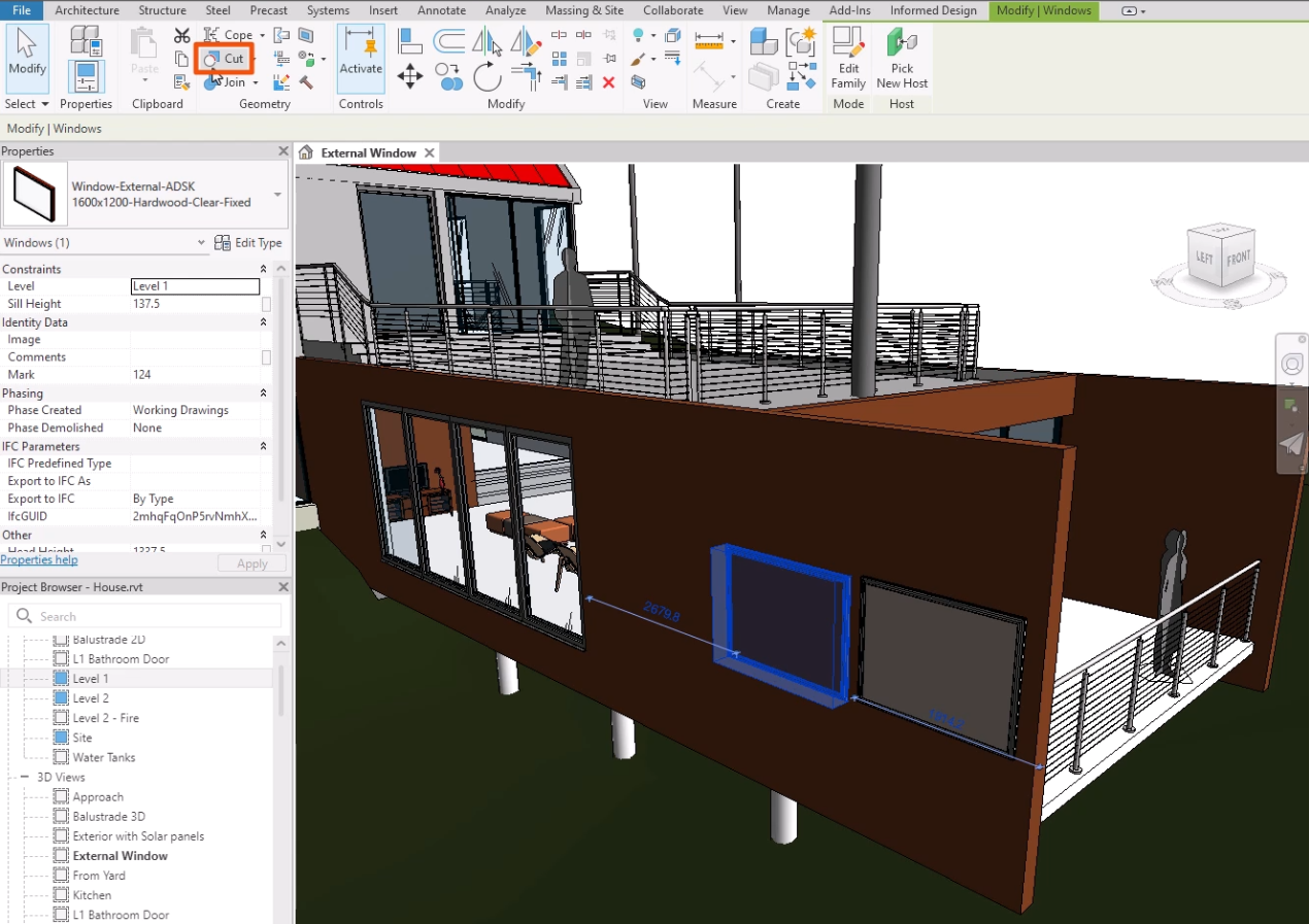
- In the model, select a family.
- On the Modify tab, in the Geometry panel, click Cut.
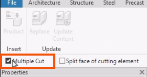
- Optionally, on the Informed Design tab, select Multiple Cut to perform multiple cuts at once.
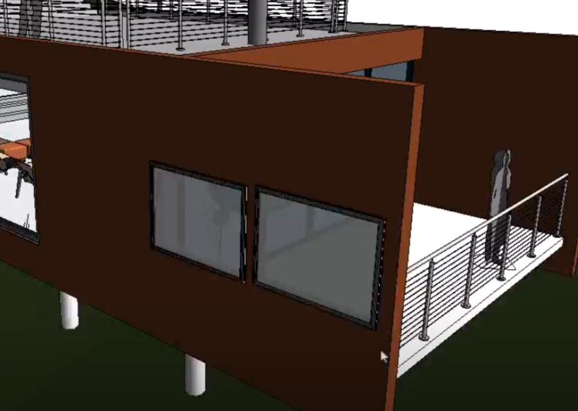
- In the model, select the object to be cut—for this example, the wall.
- Select the objects that will do the cutting—in this case, each of the two windows.
The void body removes intersecting geometry from the existing Revit object.