 AutoCAD
 AutoCAD LT
 Fusion
 AutoCAD Revit LT Suite
 Architecture, Engineering & Construction Collection
 Revit
Revit Civil 3D
 BIM Collaborate Pro
 Product Design & Manufacturing Collection
 Maya
Maya Inventor
 Navisworks
 3DS Max
 Fusion Extensions
Assign check valves to pipes and define them as open or closed, in preparation for a steady state analysis.
Tutorial resources
These downloadable resources will be used to complete this tutorial:
Transcript
00:04
Some pipes in the model may be closed or contained check valves to allow only a
00:08
unidirectional flow.
00:11
In this exercise,
00:12
you define closed pipes as closed and add a check valve tag to all
00:16
pipes with check valves to get your model ready for a steady state analysis
00:21
to begin.
00:22
Double click the desired project dot APR file to open
00:26
Agis Pro.
00:28
Once the project starts,
00:29
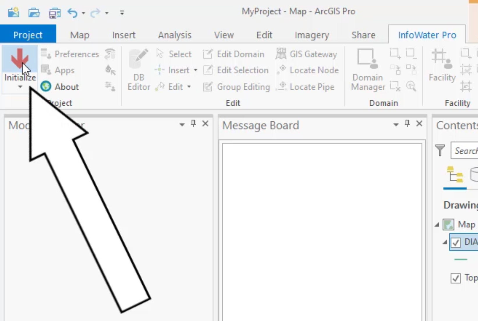
click the info water pro tab to open the info water pro ribbon
00:34
in the project panel. Click initialize
00:38
first.
00:39
You can start by color coding the different pressure zones
00:42
to help you locate the zones quickly in the model
00:45
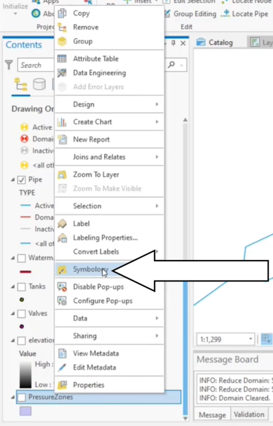
in the contents pane right,
00:47
click pressure zones and select symbology
00:51
under primary symbology. Expand the dropdown list and select unique values,
00:58
then expand the field. One dropdown and select zone.
01:04
Find the three locations where the system connects between pressure zones.
01:08
Two and three.
01:12
The very North has a pressure reducing valve or PRV that
01:16
reduces the pressure as flow goes from zone 3 to 2.
01:21
The other locations have open pipes connecting the pressure zones.
01:25
These pipes either need check valves or they need to
01:28
be closed to prevent water from rushing out of zone three
01:33
on the info water pro ribbon in the edit panel,
01:35
click the select tool and then select the middle crossing pipe with a pipe id of 8285.
01:43
This pipe needs to be closed during this analysis
01:46
as it is an interconnection for emergency use only
01:50
to close it
01:51
in the model explorer attribute tab expand the
01:55
tools drop down and select initial status,
01:59
choose close as the initial status option
02:02
and then click create.
02:07
Now select the southern crossing pipe with a
02:10
pipe id of 12415 which needs a check valve
02:15
in the attribute tab of the model explorer. Set the check valve field to yes
02:20
and click. Save
02:25
on the arc
02:26
GS pro ribbon map tab
02:28
navigate panel, click the full extent icon to zoom to the full extent of the model.
02:34
Once you have finished assigning check valves to the pipes,
02:37
it is good practice though not required to run
02:40
a special query and verify the changes you just made
02:44
on the info water pro ribbon in the domain panel, click domain manager
02:50
choose special query,
02:51
then select pipes and check valves using the adjacent dropdowns.
02:58
Then click, add
02:59
all pipes with check valves are added to the domain.
03:03
You can zoom to pipe 12415 which you previously changed to a check valve.
03:08
It is now highlighted
03:11
back in the domain manager. Click remove to remove your query,
03:15
choose special query,
03:17
then select pipes and initially closed using the adjacent dropdowns.
03:22
Then click, add
03:24
all pipes with an initial status to find is closed, are added to the domain.
03:29
Now zoom to see that pipe 8 285 which you changed to closed is also now highlighted
03:36
in the domain manager. Click remove to again, remove this query from the domain.
03:41
Click close
03:44
with the relevant pipes configured with check valves and the closed status.
03:48
You are now ready to run steady state simulations and review the results.
You can define pipes in a model to be open or closed, and whether or not they contain check valves to allow only a unidirectional flow.


The very north has a pressure reducing valve, or PRV, that reduces the pressure as flow goes from zone 3 to zone 2. The other locations have open pipes connecting the pressure zones. These pipes either need check valves, or they need to be closed to prevent water from rushing out of zone 3.


Once you have finished assigning check valves to the pipes, it is good practice (though, not required) to run a special query and verify the changes you just made.


