Sheet metal fabrication software
Autodesk Fusion for sheet metal fabrication
Autodesk Fusion for sheet metal fabrication
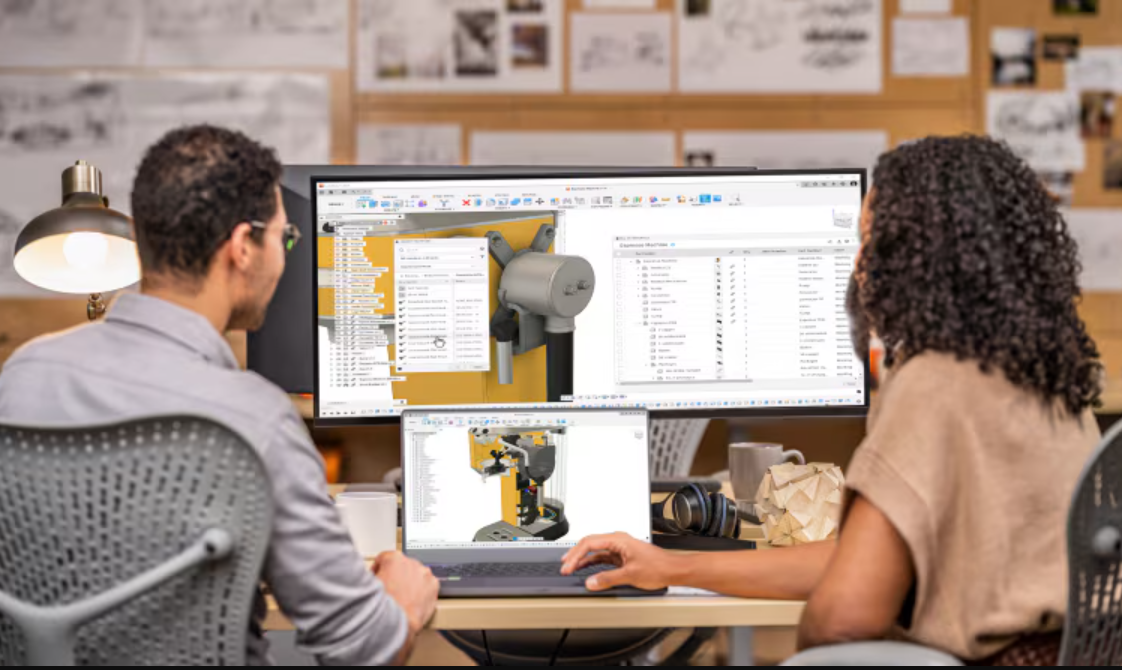
Autodesk Fusion streamlines sheet metal fabrication and design, allowing you to design, test, document, and fabricate in a single integrated product development tool.

What is sheet metal design?
What is sheet metal design?
Sheet metal fabrication is a process that involves creating metal structures and components by cutting, bending, and assembling sheet metal. The process usually begins with cutting, which is acheived through various methods such as shearing, laser cutting, waterjet cutting, or plasma cutting, to shape the metal into the desired dimensions. After cutting, the metal is bent into the necessary shapes using tools such as press brakes, rollers, or other bending equipment to form angles and curves as specified by the design. The final stage involves assembling the cut and bent pieces using techniques such as welding, riveting, or adhesive bonding to construct the final structure or component.
Sheet metal design software is calibrated for the design, engineering, and manufacturing of sheet metal components and products. It provides tools and features that aid in the creation, modification, and optimization of sheet metal parts, as well as the generation of manufacturing instructions and documentation.
Sheet metal fabrication process
Sheet metal fabrication involves several steps to transform flat sheets of metal into various shapes and structures. Here are the typical steps involved in the sheet metal fabrication forming process:
Sheet metal fabrication involves several steps to transform flat sheets of metal into various shapes and structures. Here are the typical steps involved in the sheet metal fabrication forming process:
Design
Design
Detailed designs and blueprints are created using CAD (Computer-Aided Design) software, and engineers review and finalize the design to ensure manufacturability and compliance with specifications.
Detailed designs and blueprints are created using CAD (Computer-Aided Design) software, and engineers review and finalize the design to ensure manufacturability and compliance with specifications.
Material selection
Material selection
Choose the appropriate type and thickness of sheet metal based on the project requirements.
Choose the appropriate type and thickness of sheet metal based on the project requirements.
Cutting
Cutting
Shearing cuts large sheets into smaller pieces with a shear machine. Laser cutting uses a high-powered laser for precise shapes. Plasma cutting employs a plasma torch for thick metal, while waterjet cutting uses high-pressure water with abrasives.
Shearing cuts large sheets into smaller pieces with a shear machine. Laser cutting uses a high-powered laser for precise shapes. Plasma cutting employs a plasma torch for thick metal, while waterjet cutting uses high-pressure water with abrasives.
Forming
Forming
Bending involves using press brakes or other machinery to shape the metal, while rolling forms it into cylindrical or conical shapes. Stamping presses the metal into a die for specific patterns, and punching creates holes or shapes with a punch press.
Bending involves using press brakes or other machinery to shape the metal, while rolling forms it into cylindrical or conical shapes. Stamping presses the metal into a die for specific patterns, and punching creates holes or shapes with a punch press.
Joining
Joining
Joining involves assembling the formed pieces using methods like welding, riveting, bolting, and adhesive bonding. Welding melts and fuses metal pieces, riveting fastens them with rivets, bolting secures parts with bolts and nuts, and adhesive bonding uses industrial adhesives.
Joining involves assembling the formed pieces using methods like welding, riveting, bolting, and adhesive bonding. Welding melts and fuses metal pieces, riveting fastens them with rivets, bolting secures parts with bolts and nuts, and adhesive bonding uses industrial adhesives.
Finishing
Finishing
Surface treatments are applied to improve appearance, durability, and corrosion resistance. This includes deburring to remove sharp edges, polishing for a refined finish, and coating with paint, powder, or plating for protection and aesthetics.
Surface treatments are applied to improve appearance, durability, and corrosion resistance. This includes deburring to remove sharp edges, polishing for a refined finish, and coating with paint, powder, or plating for protection and aesthetics.
Inspection and quality control
Inspection and quality control
Checking the fabricated parts for accuracy, dimensions, and quality ensures that the final product meets the design specifications and standards.
Checking the fabricated parts for accuracy, dimensions, and quality ensures that the final product meets the design specifications and standards.
Assembly
Assembly
Assembling the finished components into the final product is followed by a final inspection to ensure proper assembly and functionality.
Assembling the finished components into the final product is followed by a final inspection to ensure proper assembly and functionality.

What is sheet metal forming?
What is sheet metal forming?
Sheet metal forming is a manufacturing process that transforms flat sheets of metal into desired shapes and configurations without removing any material. This process involves applying force to the sheet metal, causing it to deform plastically and take on a new, permanent shape. Primary methods include:
Stamping - Metal is pressed into a die to form specific shapes and patterns.
Deep drawing- Sheet metal is stretched into a die to create deep, hollow shapes like cups and cans.
Roll forming - Shapes the metal by passing it through a series of rollers.
Bending - creates angles and curves by deforming the metal along a straight line.
Spinning- Rotates the metal on a lathe to form symmetrical, round shapes, and stretch forming stretches the metal over a form to create complex, curved shapes.
Hydroforming - Uses high-pressure hydraulic fluid to press the metal into a die, allowing the creation of complex shapes with smooth surfaces.
What are manufacturing methods for sheet metal fabrication?
These sheet metal design and fabrication methods are used to create a wide range of sheet metal products, components, and structures for different industries and applications.
These sheet metal design and fabrication methods are used to create a wide range of sheet metal products, components, and structures for different industries and applications.

Water jet
Water jet
Pressurized water mixed with abrasives can cut through stainless steel, Inconel, titanium, aluminum, tool steel, ceramics, granite, and armor plate, with a clean edge finish.
Pressurized water mixed with abrasives can cut through stainless steel, Inconel, titanium, aluminum, tool steel, ceramics, granite, and armor plate, with a clean edge finish.

Laser
Laser
A gas laser, such as a CO2, is transmitted through a beam, guided by mirrors, and directed at the material at an extremely high level of precision.
A gas laser, such as a CO2, is transmitted through a beam, guided by mirrors, and directed at the material at an extremely high level of precision.

Plasma
Plasma
The plasma process uses electrically conductive gas to transfer energy from a torch to the material being cut. Developed for metals that could not be flame cut, such as stainless steel, aluminum, and copper.
The plasma process uses electrically conductive gas to transfer energy from a torch to the material being cut. Developed for metals that could not be flame cut, such as stainless steel, aluminum, and copper.
What are some sheet metal design tools?

Flanges
Flanges
A flange is a common sheet metal feature, which consists of a bend connected to stationary face, along a straight edge.
A flange is a common sheet metal feature, which consists of a bend connected to stationary face, along a straight edge.

Bend calculations
Bend calculations
Bend calculations make sure that the correct length is calculated when a sheet metal design is manufactured flat and then bent into its finished state based on a K-Factor.
Bend calculations make sure that the correct length is calculated when a sheet metal design is manufactured flat and then bent into its finished state based on a K-Factor.

Gauge tables
Gauge tables
Gauge tables define the thickness of sheet metal. There are several gauge tables depending on the material of the sheet metal, which specify the thickness for both inches and millimeters.
Gauge tables define the thickness of sheet metal. There are several gauge tables depending on the material of the sheet metal, which specify the thickness for both inches and millimeters.
Benefits of sheet metal fabrication
Customization
Sheet metal fabrication is cost-effective, especially for large-scale production. Modern techniques like laser cutting and CNC machining reduce waste and labor costs, and speed up time-to-market.
Sheet metal fabrication is cost-effective, especially for large-scale production. Modern techniques like laser cutting and CNC machining reduce waste and labor costs, and speed up time-to-market.
Durability
The durability and strength of sheet metal makes it ideal for lightweight, resilient components that withstand harsh conditions, ensuring longer lifespans and reduced maintenance costs.
The durability and strength of sheet metal makes it ideal for lightweight, resilient components that withstand harsh conditions, ensuring longer lifespans and reduced maintenance costs.
Cost-effectiveness
Sheet metal fabrication is cost-effective, especially for large-scale production. Modern techniques like laser cutting and CNC machining reduce waste and labor costs, and speed up time-to-market.
Sheet metal fabrication is cost-effective, especially for large-scale production. Modern techniques like laser cutting and CNC machining reduce waste and labor costs, and speed up time-to-market.

Why do I need sheet metal fabrication software?
Why do I need sheet metal fabrication software?
Sheet metal design and fabrication software like Autodesk Fusion includes a combination of 2D and 3D design capabilities. This allows engineers and designers to create precise models of sheet metal components. Users can define parameters such as material thickness, bend allowances, hole sizes, and other geometric features relevant to sheet metal fabrication.
Streamline your entire sheet metal design-through-fabrication workflow with one software package. Autodesk Fusion allows you to connect 2D and 3D workflows so you can create, modify, and document sheet metal designs. This makes it easy to quickly get a flat pattern into production.
NEW OFFER - Flex now starting at $99
Autodesk Flex lets you prepay with tokens for on-demand access to Fusion and advanced design and manufacturing capabilities, charged only when tools are in use. It’s ideal for project-based work or occasional access to specialized workflows. Combine Flex tokens with Fusion to:
Access advanced product development workflows on demand
Use high-value capabilities only when needed
Scale access for peak workloads
Autodesk Fusion offerings for sheet metal design and manufacture

Autodesk Fusion for Manufacturing
Autodesk Fusion for Manufacturing
Autodesk Fusion for Manufacturing is an integrated CAD/CAM platform that includes parametric modeling, design for manufacture, drawing, 3D printing, sheet-metal fabrication, and cloud-based collaboration with powerful 3-axis machining, 4 and 5-axis milling, part inspection, turn-mill, probing, deburr, advanced toolpaths, and more.
Autodesk Fusion for Manufacturing is an integrated CAD/CAM platform that includes parametric modeling, design for manufacture, drawing, 3D printing, sheet-metal fabrication, and cloud-based collaboration with powerful 3-axis machining, 4 and 5-axis milling, part inspection, turn-mill, probing, deburr, advanced toolpaths, and more.
Why choose Autodesk Fusion for sheet metal design?
Here are some top reasons to consider Autodesk Fusion for your sheet metal fabrication needs.
Here are some top reasons to consider Autodesk Fusion for your sheet metal fabrication needs.
Comprehensive sheet metal design features
Comprehensive sheet metal design features
Fusion offers a range of specialized tools tailored for sheet metal design. These tools include bend and unfold commands, sheet metal-specific parameters, corner reliefs, flange creation, and more. These features streamline the design process and enable designers to create accurate sheet metal components.
Fusion offers a range of specialized tools tailored for sheet metal design. These tools include bend and unfold commands, sheet metal-specific parameters, corner reliefs, flange creation, and more. These features streamline the design process and enable designers to create accurate sheet metal components.
Cloud-based collaboration
Cloud-based collaboration
With cloud collaboration tools, multiple users to collaborate on the same design in real time. Cloud-based software is especially useful for product design teams, where parts of the products are often designed and manufactured by different team members across various locations.
With cloud collaboration tools, multiple users to collaborate on the same design in real time. Cloud-based software is especially useful for product design teams, where parts of the products are often designed and manufactured by different team members across various locations.
Integrated CAD/CAM
Integrated CAD/CAM
Fusion combines both computer-aided design (CAD) and computer-aided manufacturing (CAM) functionalities in a single platform. This integration allows designers to seamlessly transition from creating 3D sheet metal models to generating toolpaths for manufacturing processes.
Fusion combines both computer-aided design (CAD) and computer-aided manufacturing (CAM) functionalities in a single platform. This integration allows designers to seamlessly transition from creating 3D sheet metal models to generating toolpaths for manufacturing processes.
Flexible parametric model tools
Flexible parametric model tools
Flexible parametric modeling techniques allow designers to create flexible and adaptive sheet metal designs. With parametric modeling, changes made to the design propagate throughout the model, automatically updating features and maintaining design intent. This feature is useful in sheet metal design, where modifications and iterations are common.
Flexible parametric modeling techniques allow designers to create flexible and adaptive sheet metal designs. With parametric modeling, changes made to the design propagate throughout the model, automatically updating features and maintaining design intent. This feature is useful in sheet metal design, where modifications and iterations are common.
Easy to use simulation capabilities
Easy to use simulation capabilities
Streamline the deformation-based sheet metal forming process with the sheet metal tools in Fusion. The software simplifies simulating sheet metal forming with an easy setup of loading conditions, contact conditions, fixes, displacement boundary conditions, and nonlinear material properties.
Streamline the deformation-based sheet metal forming process with the sheet metal tools in Fusion. The software simplifies simulating sheet metal forming with an easy setup of loading conditions, contact conditions, fixes, displacement boundary conditions, and nonlinear material properties.
Manufacturing support
Manufacturing support
Autodesk Fusion supports a wide range of manufacturing processes commonly used in sheet metal fabrication, including laser cutting, punching, bending, welding, and more. Computer-aided manufacturing generates toolpaths for these manufacturing processes, making it easier to translate designs into physical parts.
Autodesk Fusion supports a wide range of manufacturing processes commonly used in sheet metal fabrication, including laser cutting, punching, bending, welding, and more. Computer-aided manufacturing generates toolpaths for these manufacturing processes, making it easier to translate designs into physical parts.

Sheet metal bending calculation
Sheet metal bending calculation
Sheet metal bending calculations consider the impact of different material types on the bending factor. These calculations are used to predict the final shape and dimensional accuracy of sheet metal post-bending. Some key aspects involved in sheet metal bending calculations include:
Bend allowance - This measures the length of the neutral axis between the bend lines, or the arc length of the bend. This is added to the flange lengths to obtain the flat length of the sheet metal part.
Bend deduction - This is used to calculate the length of the sheet metal bend. It calculates bend allowance/deduction based on material thickness, bend angle, inside radius, and k-factor.
K-Factor - This is a ratio that represents the location of the neutral line with respect to the thickness of the material.
Outside Setback - This is a measure of how much a bend extends beyond its mold line.
Springback - This is the amount by which the material will try to return to its original shape after bending, due to its elasticity.
What industries use sheet metal fabrication?
Consumer goods
Used to produce household appliances, kitchen equipment, furniture, and other consumer products.

Automotive
Used for manufacturing car bodies, chassis, exhaust systems, and various structural and aesthetic components.

Medical
Important for manufacturing medical devices, equipment enclosures, surgical instruments, and hospital furniture.

Aerospace
Used for producing aircraft parts such as fuselage panels, wings, brackets, and other structural components that require high precision and durability.
Autodesk Fusion sheet metal fabrication tutorials
These tutorials will help you get started with sheet metal design and fabrication in Autodesk Fusion.
These tutorials will help you get started with sheet metal design and fabrication in Autodesk Fusion.

Create, modify, and apply sheet metal rules
Create, modify, and apply sheet metal rules
Learn to create, modify, and apply sheet metal rules. Learn how to use the flange tool and how to create a cutout across multiple faces. Learn how to build a flat pattern and use it in a drawing in Fusion.
Learn to create, modify, and apply sheet metal rules. Learn how to use the flange tool and how to create a cutout across multiple faces. Learn how to build a flat pattern and use it in a drawing in Fusion.

Getting started with sheet metal design
Getting started with sheet metal design
Learn the basics of sheet metal design in Fusion. We cover sheet metal components, rules, flanges, bends, unfolding sheet metal bodies, and flat patterns.
Learn the basics of sheet metal design in Fusion. We cover sheet metal components, rules, flanges, bends, unfolding sheet metal bodies, and flat patterns.

Design a sheet metal model
Design a sheet metal model
Learn how to design a sheet metal model using Fusion. See how to parametrically edit sheet metal models and how to set up a library for sheet metal rules. Also, learn about downstream manufacturing workflows for sheet metal models.
Learn how to design a sheet metal model using Fusion. See how to parametrically edit sheet metal models and how to set up a library for sheet metal rules. Also, learn about downstream manufacturing workflows for sheet metal models.
Get started with sheet metal design with Autodesk Fusion
History of sheet metal fabrication
Sheet metal fabrication dates back to ancient Egypt and Mesopotamia, where metal was hand-hammered into tools and decorative items. The Industrial Revolution brought machines like the rolling mill and press brake, increasing precision and efficiency. The 20th century brought the introduction of laser cutting, CNC machines, and automation, further enhancing the industry's capabilities. Today, advanced software and machinery produce a wide range of products for various applications.
Sheet metal fabrication dates back to ancient Egypt and Mesopotamia, where metal was hand-hammered into tools and decorative items. The Industrial Revolution brought machines like the rolling mill and press brake, increasing precision and efficiency. The 20th century brought the introduction of laser cutting, CNC machines, and automation, further enhancing the industry's capabilities. Today, advanced software and machinery produce a wide range of products for various applications.
Sheet metal design and fabrication frequently asked questions (FAQs)
There are a few ways to create sheet metal components in Autodesk Fusion. You can create a new sheet metal component using the sheet metal rule. The rule uses your settings for material thickness, bend radius, and corner relief. You can also create a sheet metal component from scratch. You use sketch commands to create a profile for a base face or an initial contour flange. Then you exit the sketch and create your sheet metal face and flanges. Default rule is used but you can change or edit used rule.
Autodesk Fusion includes direct editing and advanced surface modeling features designed to dramatically reduce the time typically necessary for high-volume design production. Validate 3D digital models as you design without needing a prototype. Stress-test and optimize in one integrated design environment. Plus, built-in sheet metal specific commands streamline work on both folded and unfolded models.
Autodesk Fusion streamlines the deformation-based sheet metal forming process. The software simplifies simulating sheet metal forming with easy setup of loading conditions, contact conditions, fixes and displacement boundary conditions, and non-linear material properties.