Exercise 17–Detailing
In Revit, you can create construction details directly from the model you already have or you can draw them as separate and independent drawings and diagrams. They can include both live 3D elements and overlaid two-dimensional components. You can even import and reuse standard details from AutoCAD to leverage libraries already in use in your firm’s workflow.
Catch-up file completed to this point: 17_Medical Center_Details.rvt
Create a Detail
Let’s create a simple “typical” construction detail. It starts with a view.
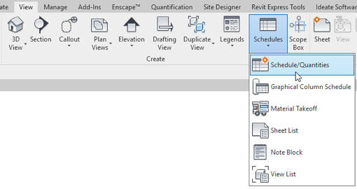
- On the View tab, click the Drafting View button.
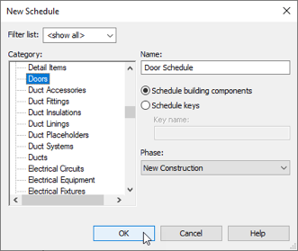
- In the New Drafting View dialog, name it “Head Detail” accept the scale and click OK (see Figure 17–1).
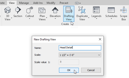
Figure 17–1 Create a new Drafting View
A Drafting View is a simple blank 2D canvas where you can draw any detail or diagram you like. It is not linked to the 3D model.
- On the Annotate tab, click the Detail Component tool (see Figure 17–2).
- On the Modify tab that appears, click the Load Family button.
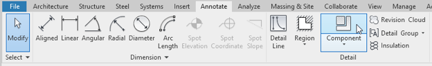
Figure 17–2 Create a Detail Component
- Browse to the: Detail Items\Div 09-Finishes\092000-Plaster and Gypsum Board\092900-Gypsum Board folder.
- Select the Gypsum Wallboard-Section.rfa family and then click the Open button.
- On the Properties palette, open the Type Selector
Like 3D families, 2D detail item families have types. Notice the various sizes (types) of drywall that were imported with this family.
- Choose the 5/8" size (see Figure 17–3).
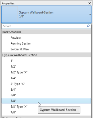
Figure 17–3 Choose a predefined size from the Type Selector
- Click two points onscreen to create a vertical piece of drywall about 12" tall.
- Zoom in on the item (see Figure 17–4).
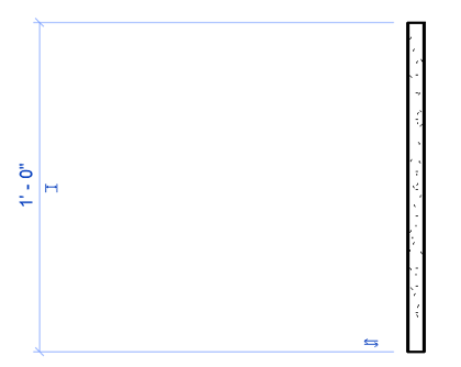
Figure 17–4 Draw a vertical piece of drywall
- Cancel the command and then copy the first one about 4" away from the first (see Figure 17–5).
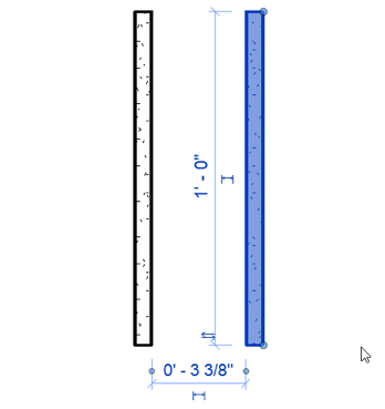
Figure 17–5 Copy the drywall component
- Using the 2D Component tool again, load additional components:
- From the Detail Items\Div 05-Metals\054100-Structural Metal Studs Framing folder, load the C Studs-Section family.
- Place an instance of the 3 1/4″ type between the two pieces of drywall.
- From the Detail Items\Div 08-Openings\081100-Metal Doors and Frames\ 081113-Hollow Metal Doors and Frames folder, load the Double Rabbet Door Frames-Section family and place an instance of the 5 3/4″ type.
- From the Detail Items\Div 01-General folder, load and place an instance of the Break Line family.
- Move and adjust the positions as indicated in Figure 17–6
All the standard Revit modification tools can help you compose your detail. Use Move, Align and any other tools as required. Note in the figure that the break line component has shape handles to adjust its size.
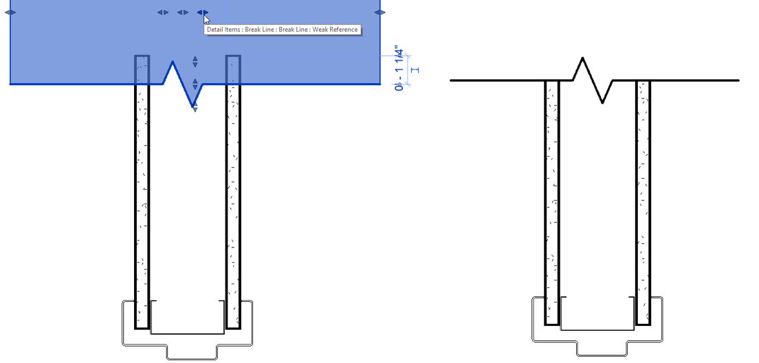
Figure 17–6 Adjust component placement
- On the Annotate tab, click the Detail line button (see Figure 17–7).
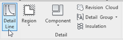
Figure 17–7 The Detail Line tool
- On the Modify tab, choose: Wide Lines from the drop-down list (see Figure 17–8).
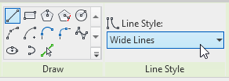
Figure 17–8 Choose the Wide Lines line style
- Draw a line in each side of the drywall to represent the ceiling.
- On the Annotate tab, click the Insulation tool (see Figure 17–9).
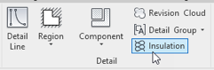
Figure 17–9 The Insulation tool
- On the Options Bar, adjust the Width to: 3".
- Draw insulation inside the wall (see Figure 17–10).
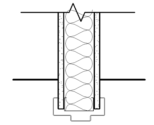
Figure 17–10 Add insulation and lines to represent the ceiling
Notice that the insulation appears in front of the break line.
- Select the insulation. On the ribbon, click the Send to Back button (see Figure 17–11).
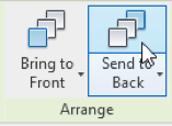
Figure 17–11 Send the insulation to the back
Add Notes
To finish the detail, add some annotation.
- On the Annotate tab, click the Text tool (see Figure 17–12).
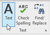
Figure 17–12 The Text Notes tool
- On the Modify ribbon, click the Two Segments Leader option.
- From the Type Selector, choose: 3/32″ Arial.
- Click first where you want the arrowhead, next click where the elbow of the leader should be, finally click to place the text.
- Type in the note. Click away from the note (in empty space) to finish typing. (Do not press enter).
- Repeat the process to add several notes (see Figure 17–13).
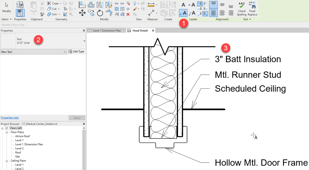
Figure 17–13 Run the text tool, configure options and begin typing
- Repeat any of the previous steps to add any finishing touches (see Figure 17–14).
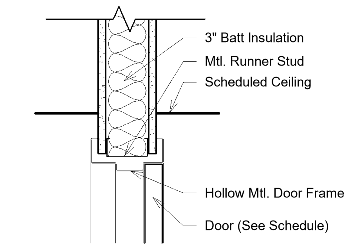
Figure 17–14 Add additional lines and text to finish the detail
Import a Detail
In addition to drawing details from scratch, you can also reuse them from other projects.
- On the Insert tab, click the Insert from File drop-down button and choose: Insert Views from File (see Figure 17–15).
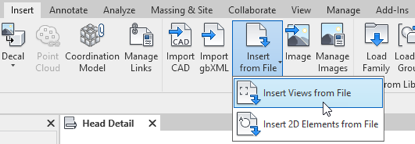
Figure 17–15 Insert a detail view from another file
- Browse to the dataset folder and select the: Door - Jamb Detail.rvt file and then click Open.
This file contains only one detail. But you can include several details in a single file and then import them in a single step.
- In the “Insert Views” dialog, accept the defaults and click OK (see Figure 17–16).
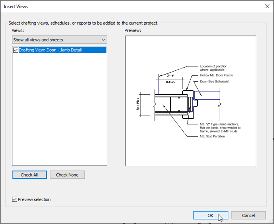
Figure 17–16 Select the detail(s) to import and then click OK
- Click OK again to dismiss the “Duplicate Types” message. This simply indicates that some types already exist in the host file.
This process makes it easy to reuse views, but please note that this works with 2D views only.
Import a CAD Detail
- Using the process above, create another Drafting view and name it: CAD Import.
- On the Insert tab, click the Link CAD button (see ).
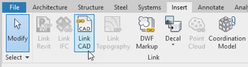
Figure 17–17The Link CAD tool
- Browse to and select the: Detail.dwg file and then click Open (see Figure 17–18).
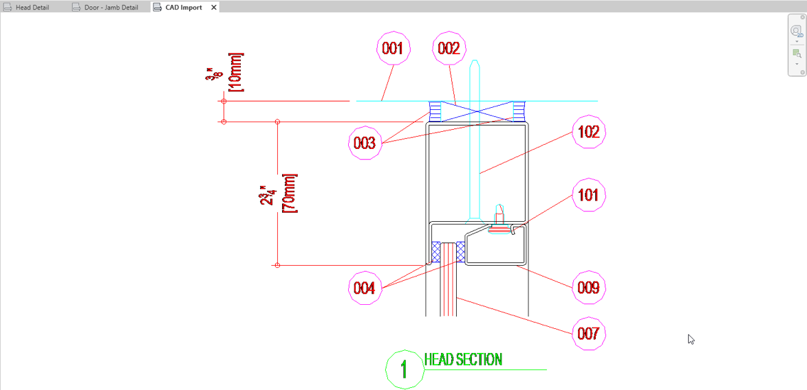
Figure 17–18 Link in a CAD file to use as a detail
- Zoom to Fit (or press zf).
This is a simple storefront detail downloaded from the Internet. Notice that the results are not that great. There are many options available to help Revit correctly interpret the CAD data being imported.
- On the Import panel title bar, click the small dialog launcher icon (see Figure 17–19).
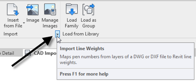
Figure 17–19 We can customize the way that colors from a CAD file match to Revit line weights
- In the “Import Line Weights” dialog, make the following edits: Color 3 – Line Weight: 4, Color 4 – Line Weight: 2, Color 6 – Line Weight: 3, Color 7 – Line Weight: 4 (see Figure 17–20).
If you prefer, you can use the Load button and load the saved version of this file instead: Lineweights.txt.
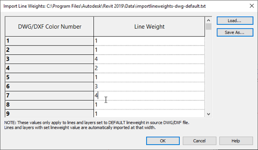
Figure 17–20 Edit the Color to Line Weight mapping table
- Select the CAD link instance onscreen. Unpin it using the icon in the middle of the link or press up. Delete the link.
- Click the Link CAD button again.
- Select the same file, but this time change Colors to: Black and White and set the Import Units to: Millimeter (see Figure 17–21).
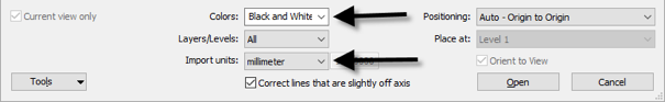
Figure 17–21 Change the color and units settings before linking
- Click Open to complete the link. Then Zoom to Fit again.
Notice that this time the file’s lines are all black and they are also using line weights. This detail is very small however, so the line weights look too heavy. Let’s adjust the scale to fix this.
- Change the scale of the view to: 6"=1'-0".
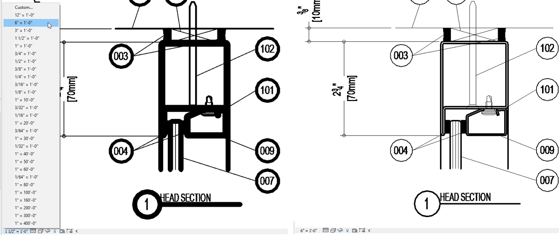
Figure 17–22Change the view scale to make the line weights display better
Note that the line weights adjust with the change in scale.