 AutoCAD
 AutoCAD LT
 Fusion
 AutoCAD Revit LT Suite
 Architecture, Engineering & Construction Collection
 Revit
Revit Civil 3D
 BIM Collaborate Pro
 Product Design & Manufacturing Collection
 Maya
Maya Inventor
 Navisworks
 3DS Max
 Fusion Extensions
Transcript
00:03
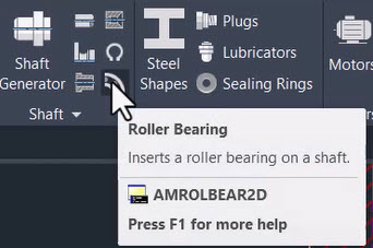
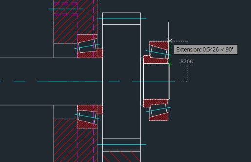
Let's use AutoCAD Mechanical to place standard bearings on a shaft.
00:08
We'll modify the shaft while placing an R ring and then we'll update the drawing views to include the new components.
00:17
AutoCAD Mechanical comes with huge libraries of standard components,
00:20
such as bearings, clips, seals, fittings, and of course steel sections.
00:27
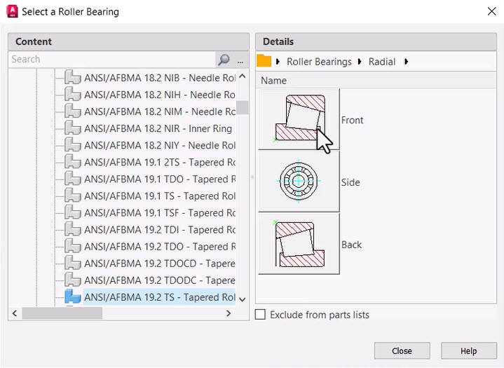
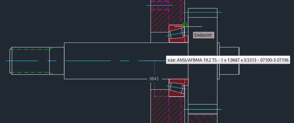
We simply use the Roller Bearing tool, which allows you have a lot of different options.
00:32
You can choose to use an axial bearing or a roller bearing.
00:36
You can choose various different classes of bearing.
00:40
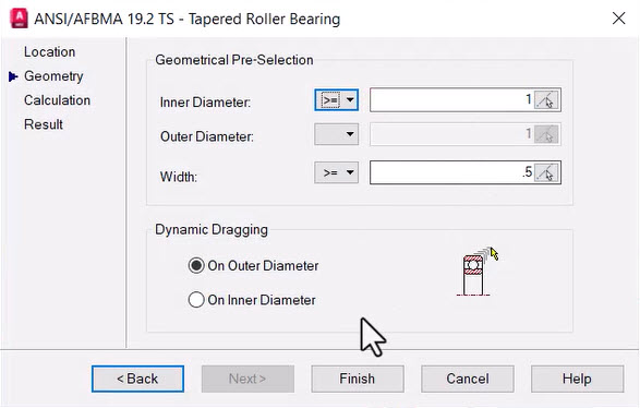
You even have the option of using calculators to suggest what bearings will work based on the types of loads the bearings will endure.
00:51
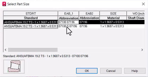
Once you've chosen the standard of bearing that you want,
00:53
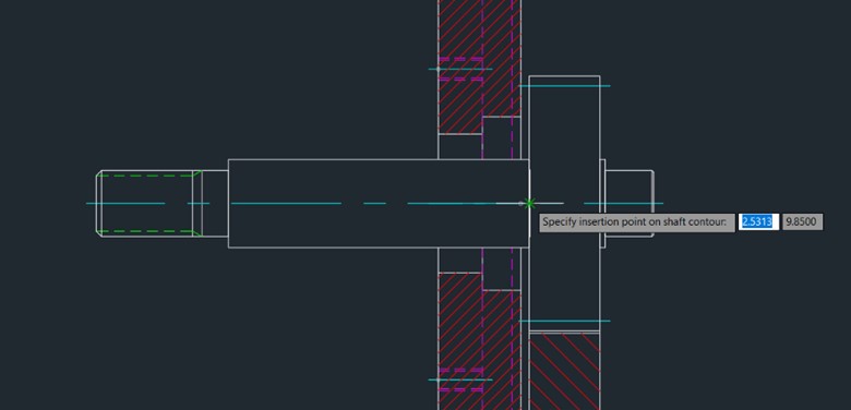
you can give it size information or you can simply drag out through the options to see what will fit in your design.
01:05
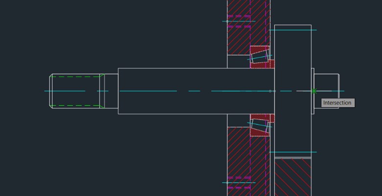
Once you've placed the bearing, you can tell it to update any sections or side views and continue on to place additional components.
01:15
Being able to pick the front, back or end view of the bearing,
01:18
makes it easy to place the bearing based on the geometry you already have, working with the geometry you need to fit.
01:25
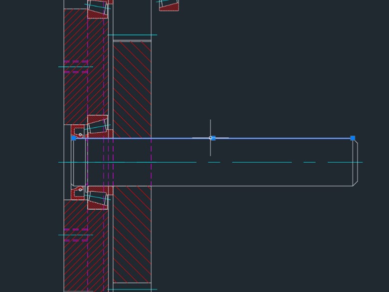
If you place a bearing on a shaft and the sizes don't line up, the shaft can even be updated to fit the bearing.
01:49
Looking at the end view, you can see an indication of the angular contact roller bearing already represented in the end view of the shafts.
01:58
Let's add another component to the shaft.
02:00
This time, we need to put a retaining ring in to keep the shaft in place.
02:07
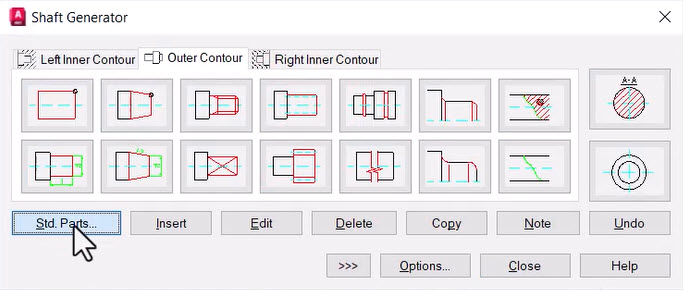
By editing the shaft, we can tell it that we want to work with standard parts that can be added to the shaft itself.
02:13
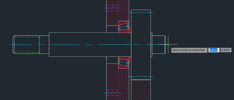
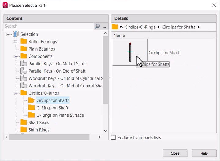
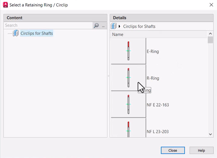
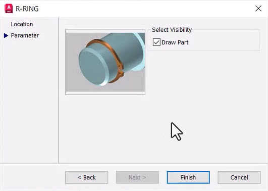
We can choose the O-Ring/Circlip tool and then select an R ring that fits the shaft.
02:21
You won't have to pick the specific size because the shaft itself will determine which R ring can be used.
02:30
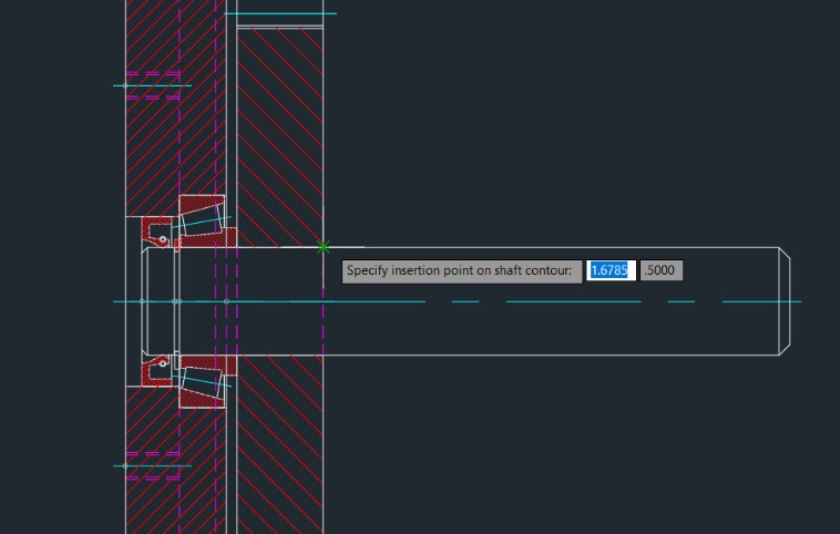
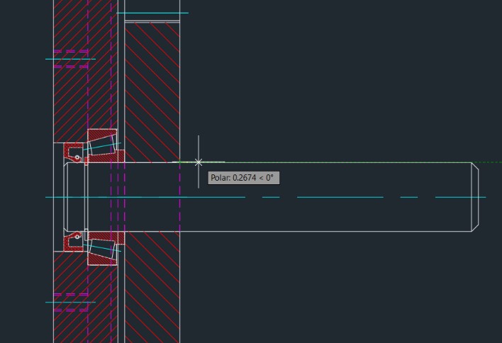
By picking the location for the ring,
02:33
AutoCAD mechanical will automatically edit the shaft to include the groove that's required and then place a view of the ring.
02:43
Once again, when closing, you'll have the option of updating any other views of the shaft.
02:49
Once done, you can take a closer look at the end view,
02:52
and see that everything has been maintained and kept up to date without having to do any additional drawing yourself.
02:59
Another feature is that all of those objects have been put on the appropriate layers with the appropriate colors.
