Preparing for VR - Exercise
In this tutorial, we will be preparing the assets for VR use in 3ds Max. Here we will be working on:
- Groups in 3ds max
- Align pivot points
- Viewport clipping
Continuing from the previous tutorial: During the import process, we choose the option to bring in each part as separate object. The purpose was that to ease the streamline of selection and removal of unwanted object. As all the objects are individually imported, we will need to group them for easy translation or rotation.
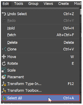
Select all the object in the scene. From the Edit Menu -> Select All or use the hot key CTRL+A.
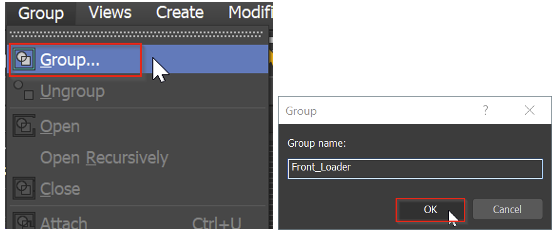
Once all the objects are selected, from the Group menu click Group… Give it a name: Front_Loader and click OK.
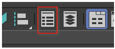
From the Main Toolbar click on the Toggle Scene Explorer or from Tools dropdown menu select Scene Explorer.
 OR
OR 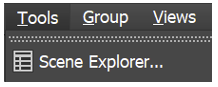
This opens the scene explorer and you will notice that everything is now in the group called FrontLoader. This makes it easier to select and move or rotate it.
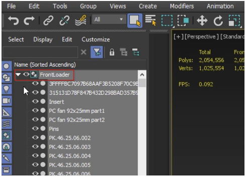
The beauty of grouping in 3ds Max: if you want to manipulate or edit objects any time in group, you can do that in a non-destructible way.
To edit or delete the object from with a group you will first need to open the group and then you will be able to select the object to edit or delete.
From the Group menu, click Open – this will temporarily open the group so that you can access its member objects.
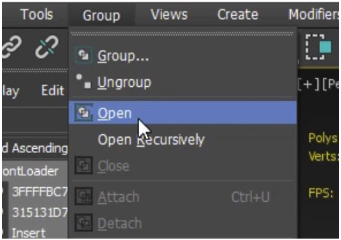
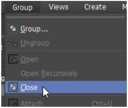
You now have the ability to select any individual object within that group to edit or delete. Once you are done, you can then close the group to restore it back to its original state.
From the Group menu, click Close.
Once you are happy with the group, we now look at the pivot point. All objects have a pivot point. You can think of the pivot point as representing an object's local center. The pivot point is the spot about which a rotation takes place, or to and from which a scale occurs.
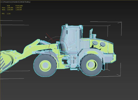
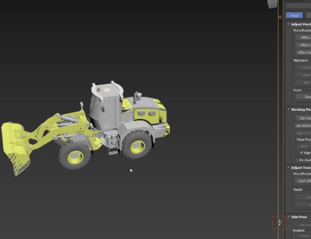
Select the FrontLoader group just by clicking on it in perspective viewport. From the main toolbar, click on the Rotate icon.

Notice that the rotate tool for FrontLoader is at the center of that object. We will be bringing this into 3ds Max Interactive and using its Pivot point as its reference. If we take the FrontLoader as it is, then it will sink halfway into the ground because its Pivot point placement. Ideally, we want the Pivot point lower to the ground, roughly to the bottom of the tire.
To adjust the Pivot point we do that by going to Command Panel - Hierarchy tab and click Affect Pivot Tab Only.
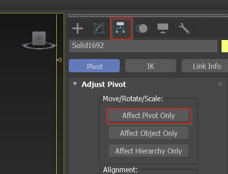
By doing this, you will see the Gizmo changes and any changes that we do will function only on the Pivot point.
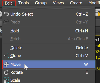
From the Edit drop down menu select Move or hit the W hot key to select the translate tool.
You can now move it manually to position the Pivot point approximately aligned to the base of the tire or you can use the easy way and use the Align tool to position the Pivot point.
From the Main toolbar click the Align tool or use the hot key Alt +A to activate the align tool.

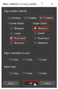
Click on any tire. Using the Align tool, I want to align the Pivot point with the minimum essentially at the bottom of the object.
Now that we have the pivot point is aligned to the ground, we will have to come out the Pivot mode. we do that by going back to Command Panel - Hierarchy tab and click one more time Affect Pivot Tab Only to come out of it.
While you are moving around in the 3ds Max viewport, you may notice some shadow appearing on the object – this is common in any 3d Software. Because of the way it represents the objects, any time when you have very thin pieces in the scene, we get Z fighting. This happens when you have 2 polygons very close to each other and the program doesn’t know which one to draw first. You may see something like a black artifact. We can fix this by enabling Viewport clipping.
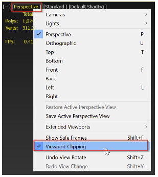
In the Perspective viewport, click on Perspective and then Viewport Clipping.
Now you have Far and near clipping plane activated. You can now chop off anything from a certain distance from the camera.
In the Perspective view, adjusting the clipping plane by one or 2 pixels will get rid of the black artifact.
File > Save or CTRL +S to Save your scene file.