Step-by-step
When importing and exporting surface data between Civil 3D and InfoDrainage, it is very important to set up the coordinate system properly, to prevent problems with model objects and surfaces not lining up. The project units and the template also must be correct to ensure a smooth data exchange.
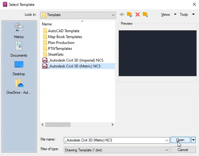
First, choose the template:
- In Civil 3D, click Start > New > Browse Templates.
- For this exercise, select the Metric templates.
Next, set the categories and coordinate system according to your local standards. This example is located in the United Kingdom—specifically, Great Britian—so the settings used here are for the UK grid coordinate system:
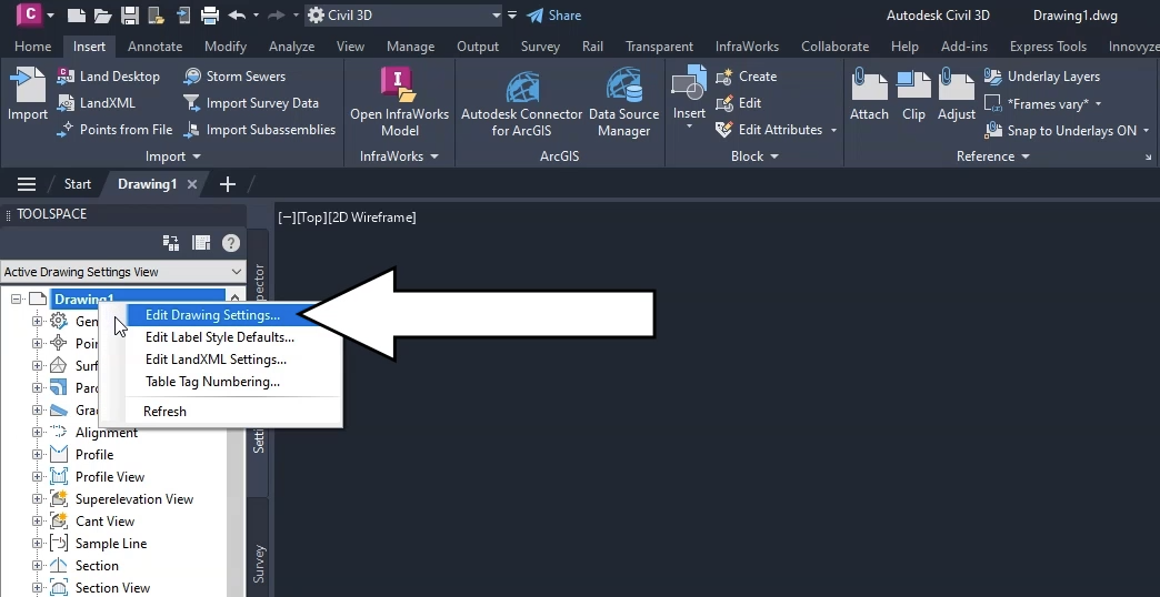
- In the Toolspace, click the Settings tab.
- Right-click the current drawing and select Edit Drawing Settings.
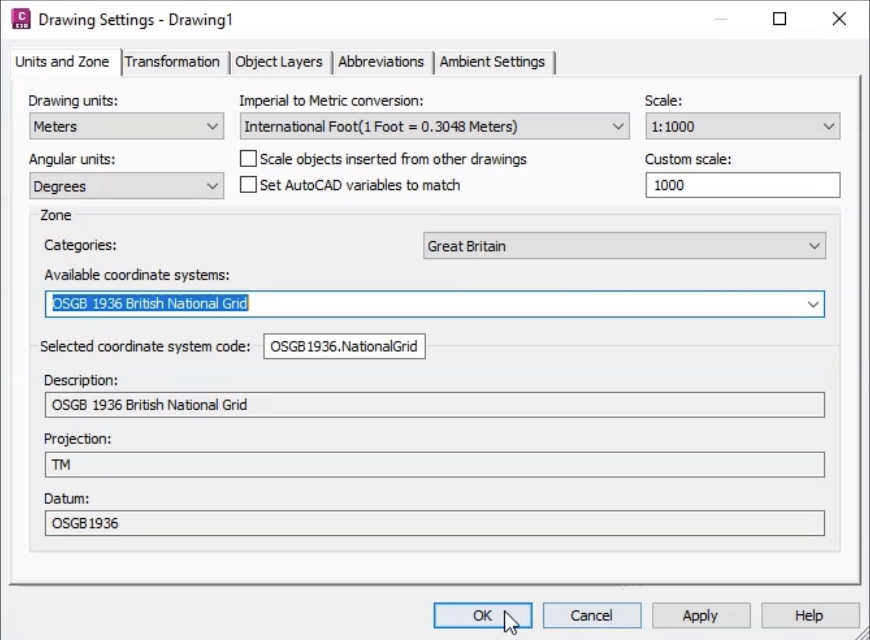
- In the Drawing Settings dialog, under Drawing units, select Meters.
- Under Angular Units, select Degrees.
- Ensure that the Imperial to Metric conversion drop-down is set to International Foot.
- Ensure that the Scale is set at 1:1000.
- In the Zone group, expand the Categories drop-down and select Great Britain.
- Ensure that Available coordinate systems is set to OSGB 1936 British National Grid.
- Ensure that Selected coordinate system code and Description are also set to OSGB 1936 British National Grid.
Next, set up the surface data used to define manhole cover levels and pond perimeter levels.
- On the ribbon, Insert tab, Import panel, click LandXML.
- In the file browser, navigate to and select the file Road1.xml from the dataset.
- Click Open.
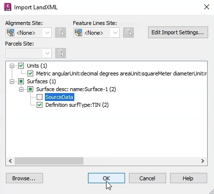
- In the Import LandXML dialog, in the tree view, expand the Surfaces node.
- Expand the Surface description node.
- Deselect the SourceData node.
- Click OK.
- If any information boxes appear, Close them.
The surface model appears in the drawing window.
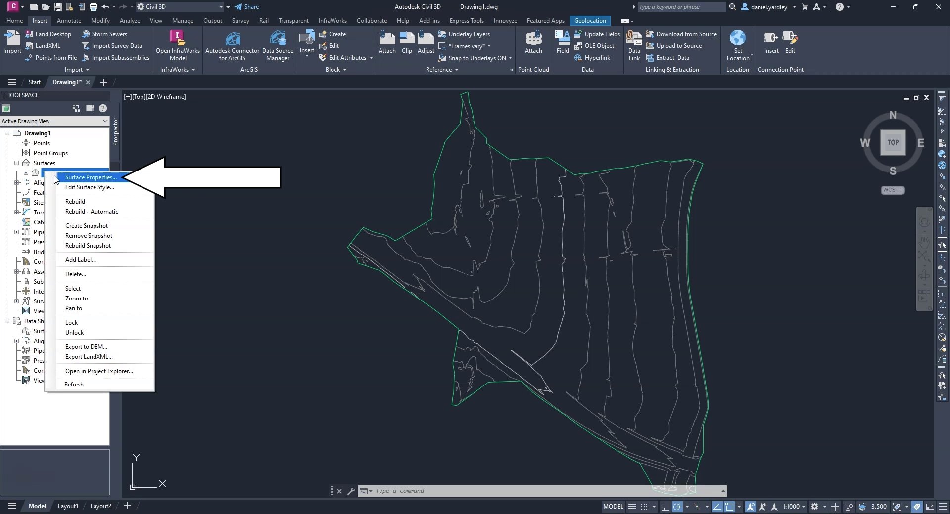
- In the Toolspace, click the Prospector tab.
- Expand Surfaces.
- Right-click Surface1 and select Surface Properties.
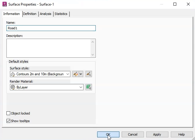
- In the Surface Properties dialog, rename the surface “Road1” to match the surface data.
You could also add a description or edit the default styles, but for this exercise, leave them as-is.
- Click OK.
The template, coordinate system, and surface file are now all configured.
IMPORTANT: For your local projects, you would configure these settings to match your local standards.


