Step-by-step
When preparing to import an InfoDrainage file into Civil 3D, after the coordinate system, template, and project units have been configured, the pipe network catalog must be set. The pipe networks featured in Civil 3D reference a part catalog and a parts list that define the size, shape, and behaviors of the pipes and structures that you insert into drawings.
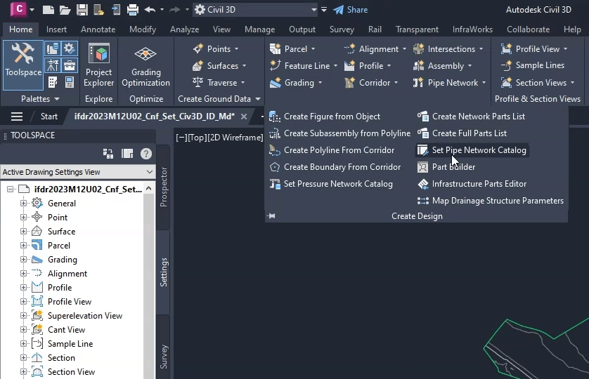
- On the ribbon, Home tab, Create Design panel, click Set Pipe Network Catalog.
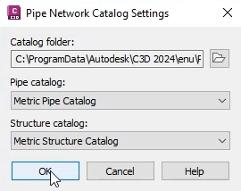
- In the Pipe Network Catalog Settings dialog box, expand the Pipe catalog drop-down and select the Metric Pipe Catalog for this exercise.
- Expand the Structure catalog drop-down and select the Metric Structure Catalog.
- Click OK.
Next, create the parts list—a focused subset of the pipe network catalog including the specific parts to be used in the pipe network:
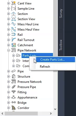
- In the Toolspace, click the Settings tab.
- Under Pipe Network, right-click Part Lists and select Create Parts List.
- In the Network Parts List – New Parts List dialog box, click the Information tab.
- In the Name field, type “InfoDrainage Specific”.
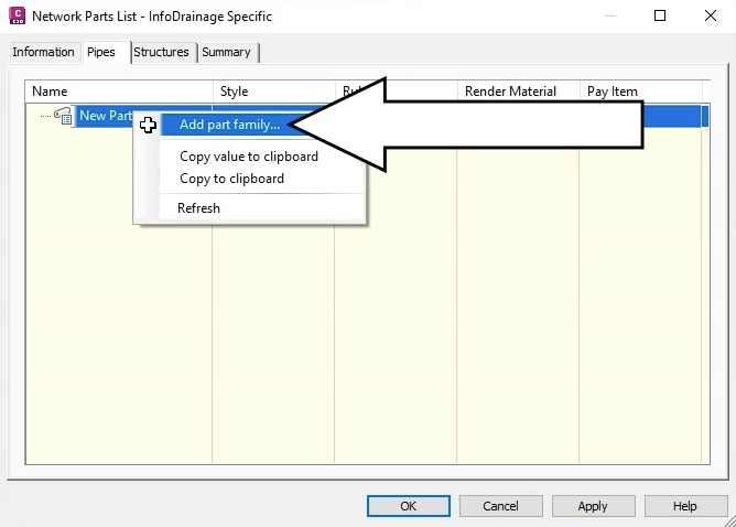
- Click the Pipes tab.
Note that the name of the dialog box updates to match the name entered.
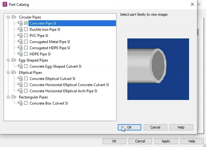
- Right-click New Parts List and click Add part family.
- In the Part Catalog, under Circular pipes, choose the Concrete Pipe SI part family.
- Click OK.
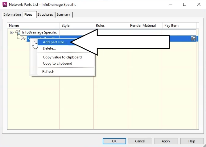
- Back in the Network Parts List – InfoDrainage Specific dialog box, click the Pipes tab.
- Under Name, expand the node and select Concrete Pipe SI to highlight it.
- Right-click Concrete Pipe SI and select Add part size.
- In the Part Size Creator, for the Wall Thickness property, enable Add all sizes.
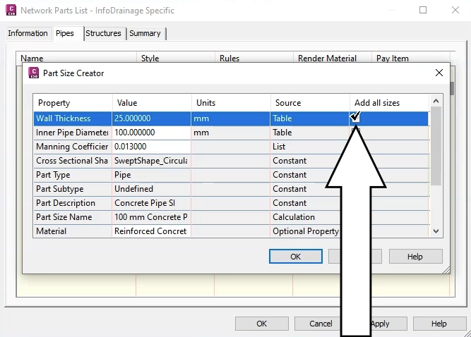
- In the Inner Pipe Diameter row, enable Add all sizes.
- Click OK.
Repeat this process to add the structures parts:
- Click the Structures tab.
- Right-click New Parts List and click Add part family.
- In the Part Catalog, under Junction Structures with Frames, select the family Concentric Cylindrical Structure SI.
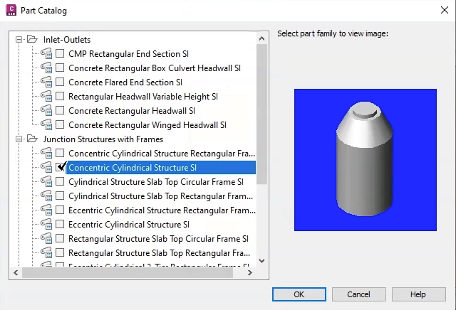
- Click OK.
- Back in the Structures tab, expand the node and select Concentric Cylindrical Structure SI to highlight it.
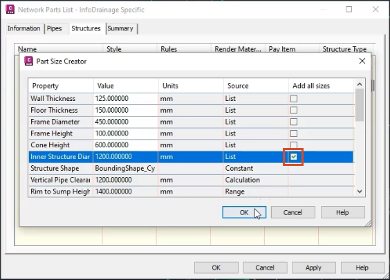
- Right-click Concentric Cylindrical Structure SI and select Add part size.
- In the Part Size Creator, for the Inner Structure Diameter, enable Add all sizes.
- Click OK to close the Part Size Creator.
- Click OK again to exit the Network Parts List – InfoDrainage Specific dialog box.
IMPORTANT: The sizes provided in the part catalog are standard sizes. If you have non-standard pipe sizes in your network, you need to use a different procedure.
Also, parts lists are saved with the drawing file, but you must designate the catalog that the parts lists reside in. This is why the parts lists are subsets of the catalog.
- Click Application menu > Save As.
- For this exercise, name the file “Surfacecreated.dwg”.
- Click Save.


