Step-by-step guide
UPC scripts allow you to represent the valves and pump stations within a water supply system that may be controlled by a more complex set of rules with multiple conditions. In this example, a UPC script sets a valve control to perform a rezone exercise following a pipe rupture.
- From the Model Group window, expand the UPC Model group.
- Double-click the UPC Network to open the UPC Network and UPC Control in the GeoPlan.
- In the Scenarios toolbar, expand the Select scenario drop-down and select Pipe break.
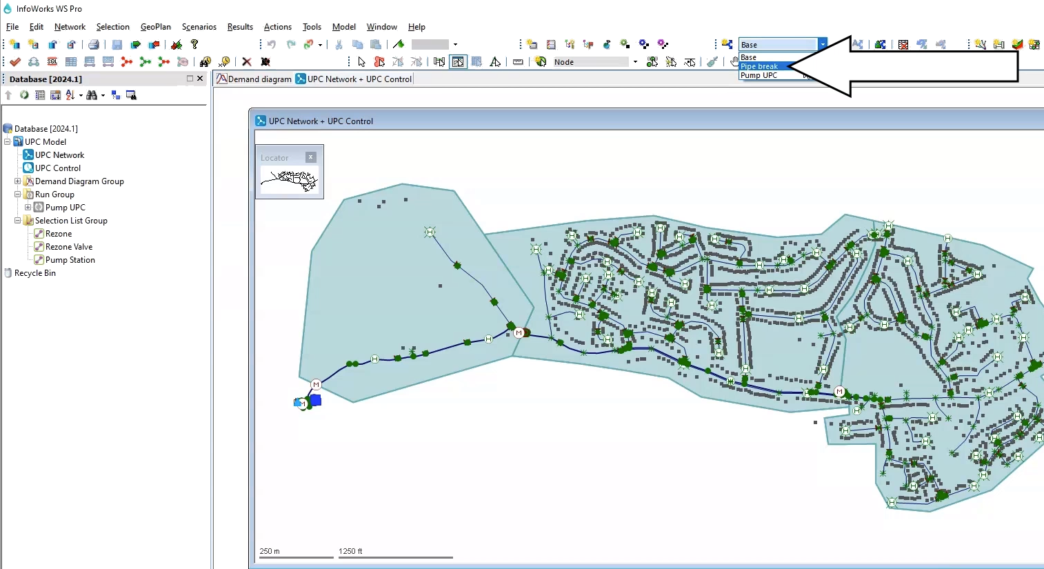
For this example, Pipe 109755 has been set to rupture between 08:00 and 12:00. When this rupture occurs and leaves the downstream network without water supply, the mitigation method is to rezone the DMA using valve 234298.
- From the Model Group, drag the Rezone Valve selection list and drop it onto the GeoPlan to identify valve 234298.
- In the Tools toolbar, click the Properties tool.
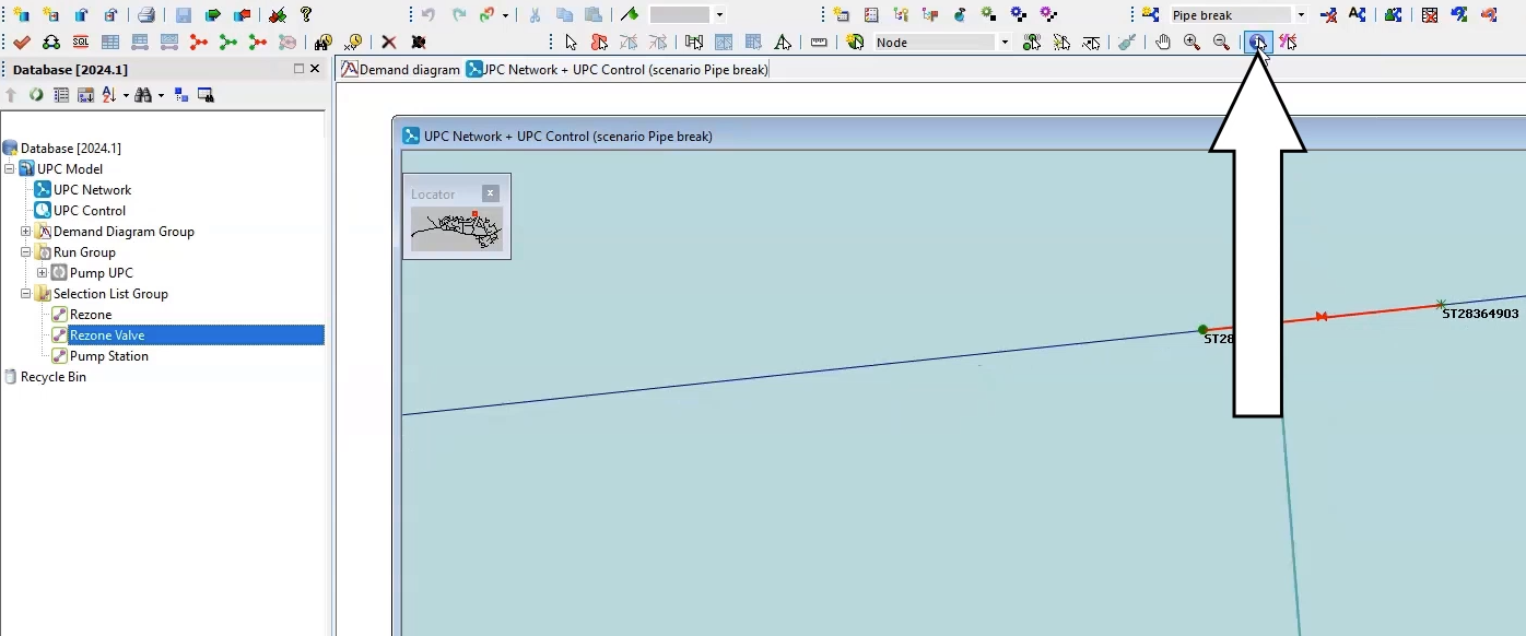
- On the GeoPlan, select valve 234298 to open the Properties window.
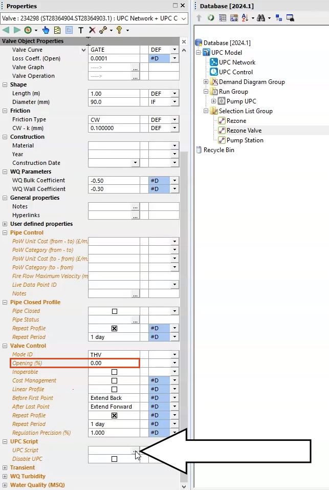
The Valve Control option is currently set to an Opening percentage of zero, meaning the valve is closed.
Now, create a UPC script that instructs the valve to open when there is a supply incident in the network, and then close when the network behavior returns to normal.
- In the Properties window, expand UPC script.
- In the UPC Script field, click the More (…) button to open the UPC Script Window.
- From the dataset provided for this tutorial, open the Pump UPC.txt file.
- Copy the lines of code provided.
- In the UPC script dialog box, Paste the code into the text field.
- Click Test to check for errors or syntax warnings.
- When the message reports no warnings or errors, click OK.
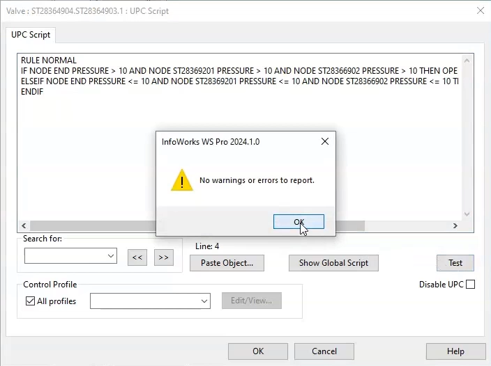
- Click OK again to close the UPC Script window.
- Commit the changes to the database.
To run the Pipe break scenario:
- In the Model Group, right-click the Run Group and select New > Run.
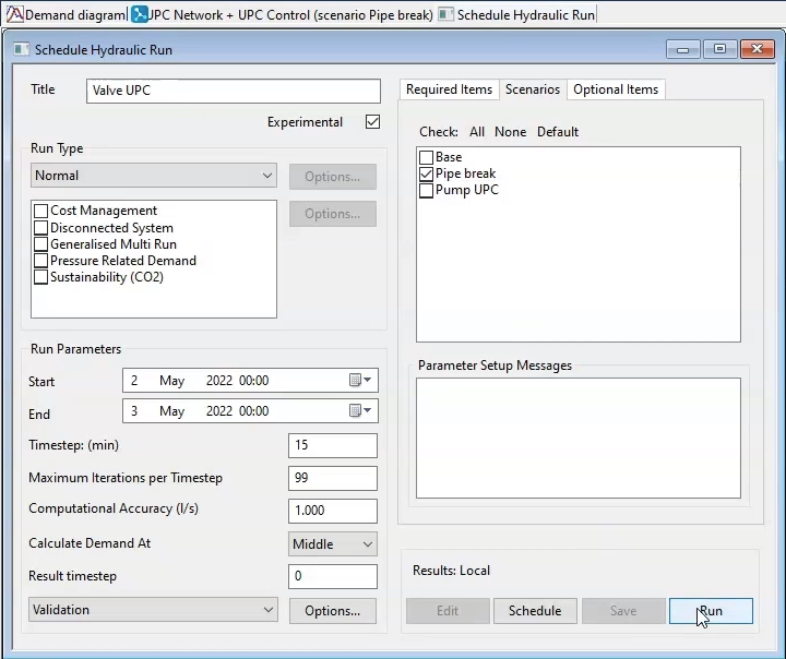
- In the Schedule Hydraulic Run dialog box, in the Title field, enter “Valve UPC”.
- Select Experimental.
- From the Model Group, drag the UPC Network into the Schedule Hydraulic Run dialog box and drop it into the Network group box.
- Click the Scenarios tab.
- Deselect the Base scenario.
- Enable the Pipe break scenario.
- Click Save.
- Click Run.
- When it finishes, from the Model Group, drag the Base simulation and drop it onto the GeoPlan.
- To identify and select the pressure control point and the valve, drag the Rezone selection list and drop it onto the GeoPlan.
Now, graph the results:
- In the Operations toolbar, select Graph selected objects.
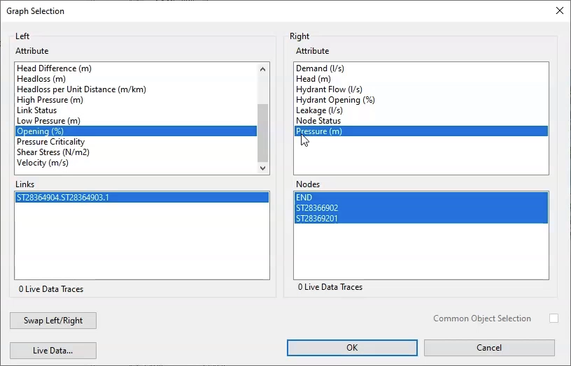
- In the Graph Selection dialog box, from the Left group box, select Opening (%).
- From the Right group box, select Pressure (m).
- Click OK.
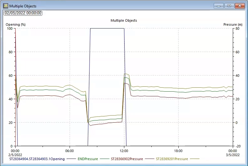
In the resulting graph, you can see that as the pressure drops at the control points, the rezone valve opens to allow water to bypass the rupture. Once the pipe is mended and the flow is restored, the rezone valve closes.
