00:08
Let's talk about the circuits now in AutoCAD Electrical.
00:11
Circuits is any combination of electrical objects
00:15
that we want to be able to manipulate
00:17
as a group within our AutoCAD Electrical project.
00:21
So a circuit could be just a combination
00:23
of a single component in a wire or two components,
00:27
two components in the wires that connect them.
00:29
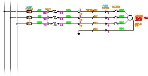
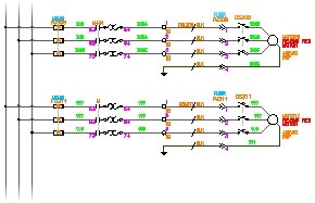
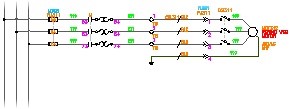
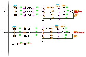
Or it could be as big as, say, the motor circuit you see here.
00:33
It could even be as big as the entire drawing you see here.
00:36
Circuits can be, like I said, any combination
00:39
of electrical objects that we want
00:41
to be able to control and work with as a group.
00:45
Now, we can save these circuits and actually
00:48
use them for a later time if it's something you're
00:50
using over and over again.
00:52
So we're going to talk now about how to move, copy, and save
00:59
In this case, I am going to be talking about this entire motor
01:03
circuit that we see here.
01:05
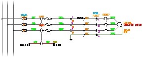
Let's say that I dropped it in, but I actually
01:07
want to move the whole thing down one rung
01:10
because I want to be able to gain space to put something
01:13
else into my ladder.
01:14
You would not want to just use AutoCAD move.
01:17
If you do that, none of the components
01:20
will then update with their new locations and new information.
01:23
Nor would they then update their panel components
01:27
that are associated with them with that updated information.
01:30
So we want all of this to stay connected and stay intelligent,
01:33
which is why we have tools to do this.
01:35
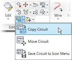
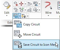
Move and Copy Circuit are up in the Edit Components area here.
01:40
I'm going to start with Move, and then we'll do a Copy.
01:43
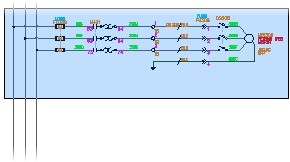
So Move Circuit works just like AutoCAD Move.
01:46
It allows you to do a Windows select around
01:48
all of your objects, and it allows
01:50
you to pick a base point.
01:52
It also will work, so be careful what you grab,
01:55
if you do a crossing window versus a regular window.
01:58
I would not want the crossing window
01:60
because I don't want to grab those three phase bus
02:02
lines that are running here.
02:04
Once I hit Enter and I've selected my objects,
02:06
I'm then going to choose my base point
02:09
as this connection at 308, and I'm
02:12
going to drop this down to 309.
02:16
Now, you can see it go through the updating of that wiring
02:19
information and update all of the tags and the wire numbers
02:27
to be associated with its new location.
02:31
We'll let it do its thing.
02:33
And now it actually sees that there
02:35
are 10 objects that need to be updated outside of this drawing
02:39
to be able to match this existing drawing.
02:42
Always say Yes, Update.
02:43
I'm only going to click Skip because we
02:45
don't need to see it go through that in this exercise.
02:47
But that is definitely something you want to say yes to.
02:50
You can see everything was updated with the new locations
02:53
and new information on it.
02:55
So now let's say I want to copy this
02:57
because I want to fill out the rest of the drawing with more
03:00
I'm going to come back up, grab a copy circuit,
03:04
do the exact same thing I did for move.
03:09
Grab that same base point.
03:10
And now I'm going to start making copies.
03:13
So I'm going to click on 312, and then I'm
03:16
even going to click on 315 down here.
03:20
Now, one of the most common things
03:21
that people do in vanilla AutoCAD
03:23
is hit Escape right now.
03:25
Escape exits you out of the command that you're in.
03:29
That would be bad in this case with AutoCAD Electrical
03:31
because it wouldn't go through to do it's
03:33
updating that it needs to do.
03:35
You must hit Enter to tell it you're done with the command.
03:39
If you just hit Escape, it will just wipe you out
03:42
of the command entirely, and then it
03:43
won't do all of that special updating.
03:45
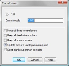
Because I hit Enter, I now see Copy Circuit Options.
03:49
And it's going to allow me to make decisions
03:51
about things I want to do with maybe wire numbers, component
03:54
tags, or terminal numbers.
03:56
Now, there aren't any wire numbers or component tags
03:59
that I need to worry about.
03:60
As you can see, they are grayed out.
04:02
But in terminal numbers, it's noticing
04:04
that there are similar terminal numbers
04:06
and that I probably don't want duplicates there,
04:09
but I more than likely either want to blank them out
04:11
so I can edit them myself or increase them.
04:14
The default is increase because you're
04:16
assuming that these are probably a part of the same terminal
04:19
strip with the same information, so they're just
04:21
going to continue increasing to build out that terminal strip.
04:25
I'll click OK, and they will all update,
04:29
and all of the rest of the components in the tags
04:31
will update as well.
04:33
Now, there may be times where you see the wire numbers go
04:35
to a question mark like you're seeing on mine right now.
04:39
That is an easy refresh of your wire numbers that you can do.
04:42
It's just noticing that there's new locations.
04:44
So while it's updating the component tags,
04:46
it doesn't update those wire numbers at the same time
04:49
to make sure that there's not a duplication there.
04:52
So now all I have to do is hit Wire Numbers again
04:54
like we did a few lessons earlier, and just hit a Tag
05:01
It takes two seconds.
05:03
And all of those wire numbers will then get updated again,
05:06
and those question marks will be gone.
05:10
Now, if I want to save this circuit so that I can use it
05:13
again because it's perhaps a motor
05:15
circuit I use all the time, that's
05:17
what we're going to do next.
05:21
So now I'm going to zoom back up.
05:22
I'm just going to take the top one that we have here.
05:25
And I am going to go back under that Edit area
05:28
and say Save Circuit to the Icon Menu.
05:33
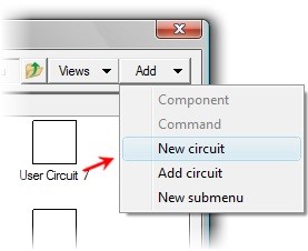
It automatically defaults to taking me
05:35
into a section of the Icon Menu called Save User Circuits.
05:40
You don't have to put it here.
05:41
You could even page out of this and go up
05:44
to Motor Wiring-- or Motor Control in this case.
05:48
And maybe I wanted to just put it right here
05:50
because I know it's a part of all the other motor
05:53
You can place this here, or we can go back
05:57
to those user circuits.
05:59
It doesn't change anything.
05:60
You can even move it after the fact as well.
06:02
So in here, I'm going to say--
06:04
I'm going to come up to Add, and I'm going to say,
06:06
I want to Add a New Circuit.
06:09
Now, I am literally building a block
06:12
and setting up everything that I'd
06:13
be doing to create a custom symbol just right
06:16
out of the navigation here.
06:17
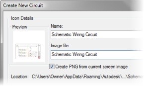
So I'm going to give it a name.
06:19
I'm going to call it Motor String.
06:22
I'm going to give it-- and I'm just
06:23
going to copy and paste this.
06:25
I'm going to give it the exact same image file
06:27
name and the exact same drawing file name.
06:30
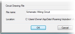
So what I'm doing here is creating on the fly
06:33
a PNG image for the Icon menu.
06:36
I am creating a W block of the full motor circuit.
06:40
And then I'm giving it a title for what it's going
06:42
to see inside the Icon Menu.
06:45
Now, I have chosen to use the Create
06:47
PNG from the screen image as opposed
06:49
to trying to create my own PNG.
06:51
You can absolutely create your own PNGs and replace this.
06:56
I'm going to click OK.
06:57
And now, if you're reading, it's asking me for my base point
07:00
So this is going to be the insertion
07:02
point of the full circuit.
07:04
Then I'm going to select all of my objects
07:06
to be included in that circuit.
07:08
And now I have a new little motor string image there
07:12
that will allow me to insert that motor
07:15
string any time I want.
07:17
And it will automatically do a special explodes.
07:20
So if you remember from the last lesson, I said do not explode.
07:24
This will do it on its own as a part of the insert
07:27
to make sure that all of those components
07:29
are broken apart into their electrical specific components
07:32
that we need to be able to edit and pull for reporting.
07:36
But it's doing it by being a part of this Circuit command.
07:40
Once I'm done, I click OK.
07:41
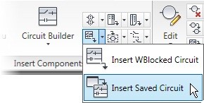
And any time I go to my Icon Menu now
07:44
and I go into Motor Control, I will see that motor string
07:47
Please take a moment to try the Move, Copy,
07:51
and Save a Circuit exercise.