| |
| |
Completion Time: 20 Minutes
|
Completion of the Terminals, Multiple level Terminals and Jumpers Lesson
| |
Objective: In this exercise, you insert terminals with wire number assignments. Then you add jumpers between terminals on the same wire networks. Finally, you associate terminals together by creating multiple level terminals.
|
| |
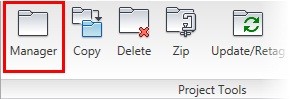
1: If the Project Manager is not displayed, on the Project tab, Project Tools panel, click Manager.
|
| |
2: If Schematic_Components_NFPA is the active project, skip to step 5. If it is open but not active in the Project Manager, do the following:
> Right-click Schematic_Components_NFPA.
> Click Activate.
> Skip to step 5.
|
| |
3: In the Project Manager, click Open Project.
|
| |
4: Browse to where you installed the exercise files. Select Schematic_Components_NFPA.wdp. Click Open.
|
| |
5: From the Projects list, click the expansion node next to Schematic_Components_NFPA to expand the drawing list.
|
| |
6: Right-click Schematic_Components_NFPA_06.dwg. Click Open.
|
| |
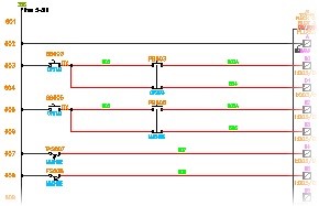
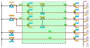
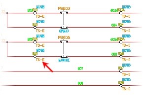
7: Zoom in to rungs 602-608.
|
| |
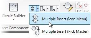
8: On the Schematic tab, Insert Components panel, Multiple Insert (Icon Menu) flyout, click Multiple Insert (Icon Menu).
|
| |
9: In the Insert Component dialog box, in the NFPA: Schematic Symbols preview area, click Terminals/Connectors.

|
| |
10: In the NFPA: Terminals and Connectors preview area, click Round with Wire Number.

|
| |
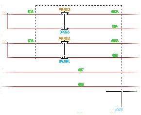
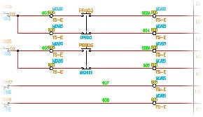
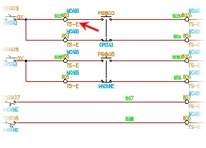
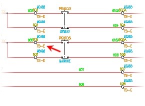
11: Draw a fence line as shown, starting below rung 606, and then moving up, to the right, and down across rungs 603-608, nearer to the PLC. Press ENTER.
|
| |
12: In the Keep? dialog box, select Keep This One. Click OK.
|
| |
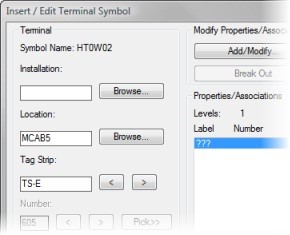
13: In the Insert/Edit Terminal Symbol dialog box, under Terminal, for Location, click Browse.
|
| |
14: In the Location Codes dialog box, from the Drawing list, select MCAB5. Click OK.
|
| |
15: In the Insert/Edit Terminal Symbol dialog box, under Terminal, for Tag Strip, type TS-E
|
| |
16: If necessary, click Details to expand the dialog box and display the Catalog Data area.
|
| |
17: Under Catalog Data, click Catalog Lookup.
|
| |
18: In the Catalog Browser dialog box, do the following:
> In the Search field, type 0115*
> Select 0115 126.01.
> Click OK.
|
| |
19: In the Insert/Edit Terminal Symbol dialog box, click OK.
|
| |
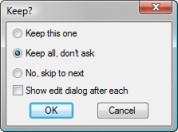
20: In the Keep? dialog box, do the following:
> Click Keep All, Don't Ask.
> Clear Show Edit Dialog After Each.
· > Click OK.
|
| |
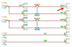
21: Notice that terminals are inserted on all crossing locations.
|
| |
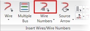
22: If necessary, to update the terminal wire numbers to match the associated wire numbers, on the Schematic tab, Insert Wires/Wire Numbers panel, click Wire Numbers.
|
| |
23: In the Wire Tagging dialog box, click Pick Individual Wires.
|
| |
24: In the drawing, select wires 603-608. Press ENTER.
|
| |
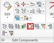
25: On the Schematic tab, Edit Components panel, Edit Components flyout, click Edit Jumper.
|
| |
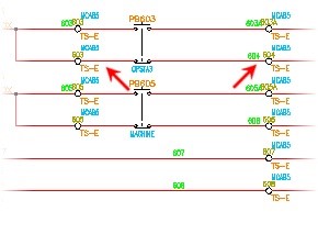
26: In the drawing, select terminal 603 on rung 603.

|
| |
27: On the command line, click on Browse.
|
| |
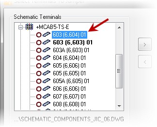
28: In the Select Terminals to Jumper dialog box, under Schematic Terminals, expand MCAB5-TSE.
|
| |
29: Select 603 (6,604) 01.
|
| |
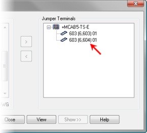
30: Click the > button to create the jumper. Click OK to close the Select Terminals to Jumper dialog box.
|
| |
31: At the Command prompt, press ENTER.
|
| |
32: In Edit Terminal Jumpers dialog box, click OK.
|
| |
33: On the Schematic tab, Edit Components panel, Edit Components flyout, click Edit Jumper.
|
| |
34: In the drawing, select terminal 605 on rung 605.

|
| |
35: Select terminal 605 on rung 606. Press ENTER.
|
| |
36: In the Edit Terminal Jumpers dialog box, click OK.
|
| |
37: In the drawing, right-click terminal 607 on rung 607. Select Edit Component.
|
| |
38: In the Insert/Edit Terminal Symbol dialog box, click Block Properties.
|
| |
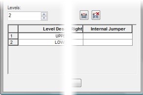
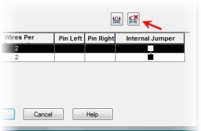
39: In the Terminal Block Properties dialog box, resize the dialog box to display all columns, including the Internal Jumper column.
|
| |
40: Select the Upper and Lower levels.
Tip: Use the CTRL selection option.
|
| |
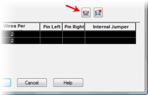
41: Click Assign Jumper. Click OK.
|
| |
42: In the Insert/Edit Terminal Symbol dialog box, click OK.
|
| |
43: Repeat the previous 6 steps on terminal 608 on rung 608.
|
| |
44: Zoom in to terminal 610 on rung 610.
|
| |
45: Right-click terminal 610. Select Edit Component from the Marking Menu.
|
| |
46: In the Insert/Edit Terminal Symbol dialog box, click Block Properties.
|
| |
47: In the Terminal Block Properties dialog box, select either one of the levels.
|
| |
48: Click Delete Jumper. Click OK.
|
| |
49: In the Insert/Edit Terminal Symbol dialog box, click OK.
|
| |
50: Zoom in to rungs 602-608.
|
| |
51: Right-click terminal 603 on rung 603. Click Terminals > Associate Terminals.
|
| |
52: Reselect terminal 603 as the master component.
|
| |
53: Select terminal 603A on rung 603. Press ENTER.
The terminal association is created.
|
| |
54: Repeat the previous 3 steps using terminals 603 and 604 on rung 604.
|
| |
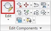
55: On the Schematic tab, Edit Components panel, click Edit.
|
| |
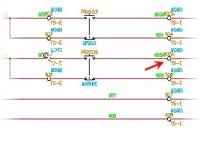
56: In the drawing, select terminal 605 on rung 605.
|
| |
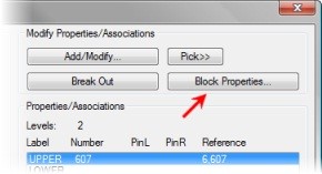
57: In the Insert/Edit Terminal Symbol dialog box, under Modify Properties/Associations, click Pick.
|
| |
58: In the drawing, select terminal 605A on rung 605.
|
| |
59: In the Insert/Edit Terminal Symbol dialog box, under Modify Properties/Associations, click Add/Modify.
|
| |
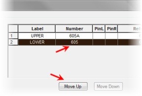
60: Under Active Association, in the grid, select Lower, 605.
Click Move Up. Click OK.
|
| |
61: In the Insert/Edit Terminal Symbol dialog box, click OK.
|
| |
62: In the Update Related Components dialog box, click Yes-Update.
|
| |
63: On the Schematic tab, Edit Components panel, click Edit.
|
| |
64: In the drawing, select terminal 605 on rung 606.

|
| |
65: In the Insert/Edit Terminal Symbol dialog box, under Modify Properties/Associations, click Add/Modify.
|
| |
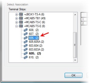
66: Under Select Association, under Terminal Strips, select terminal 606.
|
| |
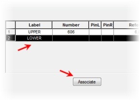
67: In the terminal strips grid, select the Lower row. Click Associate.
|
| |
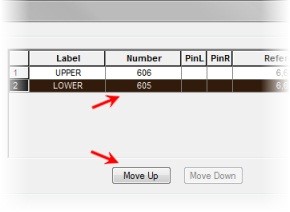
68: Under Active Association, in the grid, select Lower, 605.
|
| |
69: Click Move Up. Click OK.
|
| |
70: In the Insert/Edit Terminal Symbol dialog box, click OK.
|
| |
71: In the Update Related Components? dialog box, click Yes-Update.
This completes the exercise.
|
|