Understand closed loop hydronic systems and create hydraulic separation.
Tutorial resources
These downloadable resources will be used to complete this tutorial:
Transcript
00:04
Pressure drops and flow rates for closed loop supply
00:07
and return piping networks can be calculated in red
00:11
and the values displayed in the properties of the pump in the system.
00:15
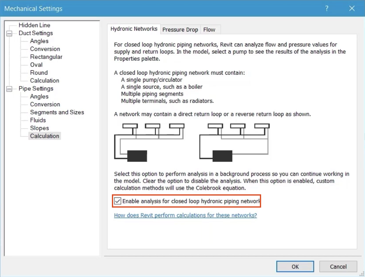
This is achieved first by creating a suitable system
00:18
that meets the criteria outlined in the mechanical settings.
00:22
And second by ensuring the option to enable analysis is checked.
00:29
Ensure the current view is set to HV
00:31
floor plans. One mec
00:35
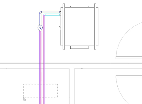
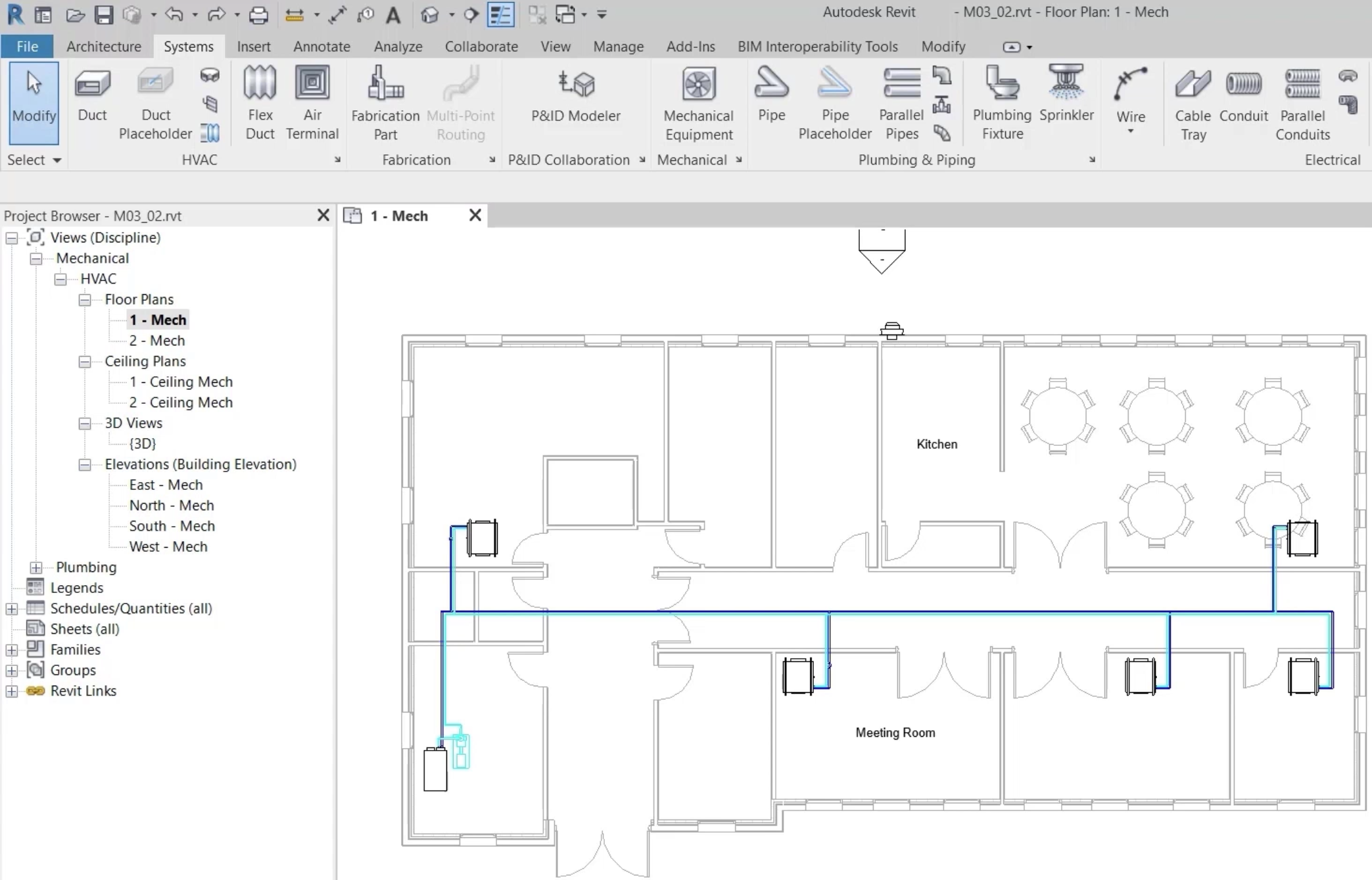
the current view shows a closed loop hydraulic piping network.
00:39
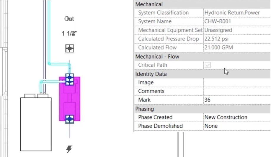
And by selecting the pump near the chiller,
00:42
the calculated values for pressure drop and
00:44
flow are displayed for the entire system.
00:48
The properties also show that the pump is part of the critical path,
00:54
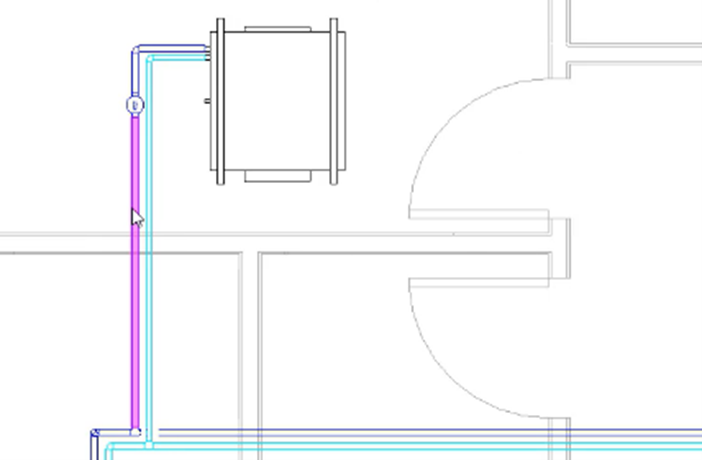
selecting any of the pipes in this chilled water
00:57
flow and return network will display the system names,
01:01
chilled water flow, 001 and chilled water, return 001,
01:09
activating the system inspector, which we'll look at in more detail.
01:12
In a later video
01:14
will also show that the main run and each of the loops
01:17
to the phone call units are part of the same physical system.
01:23
Each loop from the main run has a fan core unit
01:27
and an in line pump and in its current state,
01:30
it's not as easy to establish the same
01:32
values that are available for the entire system.
01:36
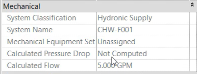
On inspection of an in line pump,
01:38
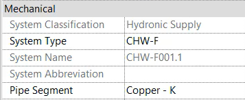
it can be seen from the properties that it is part of the chilled water flow 001 system
01:45
and the flow rate to the phone call unit is available.
01:48
But the pressure drop for this specific section is not
01:54
hydraulic separation of piping networks,
01:57
maintains physical connectivity but allows for analytical separation of loops.
02:02
So that values for specific loops within a larger system can be established.
02:09
Select the float and return pipes to the first fan core unit.
02:13
And from the ribbon select add separation,
02:19
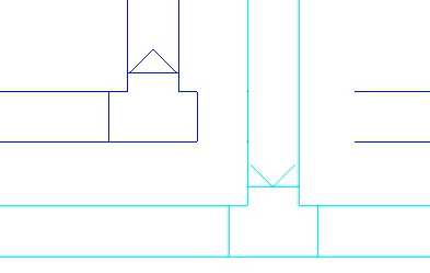
there are two indicators that separation has occurred.
02:23
Firstly, small directional symbols will appear at the point of separation.
02:29
And secondly, selecting a section of pipe will show the system name has changed,
02:37
select the section of pipe before the pump.
02:40
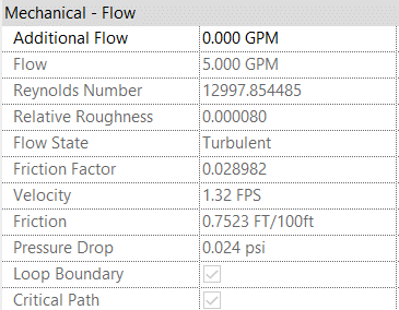
And a review of the mechanical flow properties shows that this is now considered a
02:45
loop boundary and is part of the critical path for the purposes of calculation,
02:53
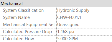
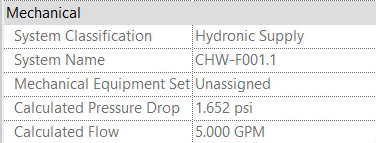
select the in line pump and note the current values for pressure drop and flow.
03:01
Any changes made in this section,
03:03
the water flow rates and pressure drop are now easier to monitor,
03:09
change the diameter of the float and return pipes to one inch.
03:21
Then review the properties at the in line pump,
03:25
then
03:26
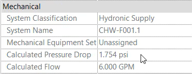
change the chilled water flow rate. At the phone
03:29
call unit to six gallons per minute
03:34
and again, review the properties at the pump.
03:40
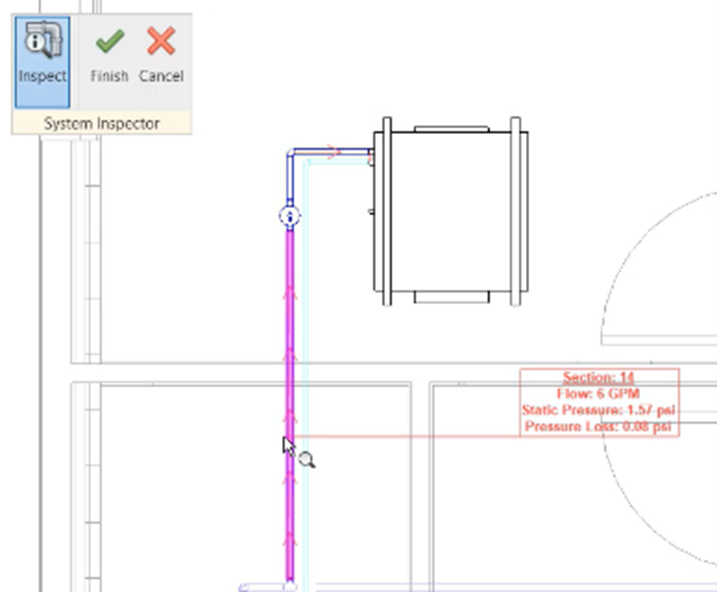
The system inspector will also see this part
03:43
of the overall system as being analytically separated.
03:48
Select the phone call unit and activate the system inspector.
03:54
Note the names of the two connected systems.
03:58
Select either one and then use the
04:00
system inspector to display the associated values
04:07
when separation is no longer required.
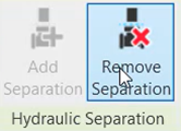
04:10
Select the original pipes and from the ribbon choose remove separation
04:18
by using hydraulic separation in the piping networks. Shown. In this example,
04:24
we have been able to review and evaluate individual piping
04:27
loops that have been separated analytically from the main system,
04:31
a workflow that allows mechanical designers to consider such areas as the
04:36
size of piping and equipments suitability at a more detailed level.