• Revit

Conceptual duct and pipe layouts

Understand and create conceptual duct and pipe layouts.

Tutorial resources

These downloadable resources will be used to complete this tutorial:


00:04

At the early stages of an mep project to create a

00:07

detailed mechanical layout can be time

00:10

consuming costly and most likely unnecessary

00:14

with duct and pipe sizes, fittings and detailed coordination.

00:18

Something to be considered at a later stage.

00:22

Single line, indicative mechanical layouts are more usual at this stage.

00:27

Moving to detailed design as the project progresses

00:32

in red,

00:32

this is taken care of by using duct and pipe placeholders,

00:37

duct and pipe placeholders carry the same intelligence as regular duct and pipe

00:41

but are represented by a single line and do not consider details such as fittings,

00:49

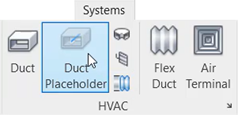
duct and pipe placeholders are found on the

00:51

rack panel and the plumbing and piping panel of the systems tab

00:56

ensure the current view is set to H VAC floor plans one mec.

01:03

In this view, the equipment has been placed only as a guide.

01:08

Let's start by creating a duct placeholder,

01:11

select duck placeholder from the ribbon.

01:13

And a review of the type selector shows that even though this is a placeholder,

01:18

the duck type can still be selected

01:21

and from the options bar, the size can be set,

01:24

giving you the option to make an early choice if required

01:28

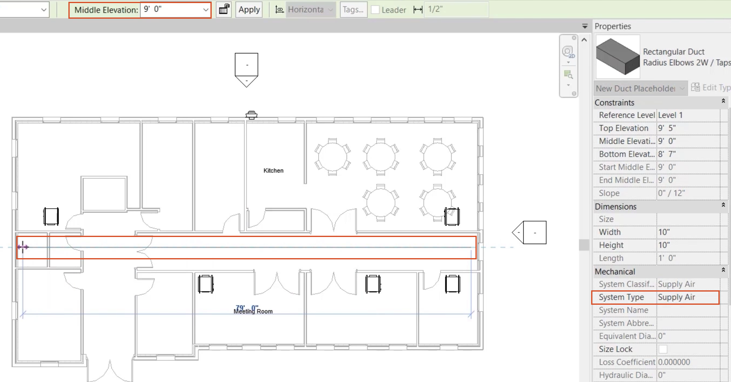
changing the system type to supply air,

01:31

leave all other options as they are and draw

01:34

a duct run along the center of the corridor

01:36

at a nominal height of 9 ft.

01:39

Then at the riser,

01:41

change the elevation to zero and select apply from the options bar,

01:48

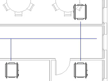
set the elevation back to 9 ft and draw branches to each of the phone

01:53

call units.

01:55

At the last two fan call units, draw a duct placeholder that crosses the main run

02:12

from the plumbing and piping panel. Select pipe placeholder

02:17

and changing the system type to chilled water flow.

02:20

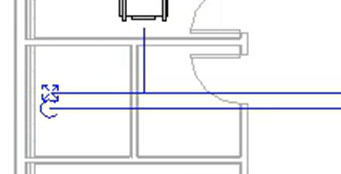
Draw a run along the corridor below the supply duct run

02:24

again at a height of 9 ft.

02:27

Then at the riser change the elevation to zero

02:30

and select apply

02:37

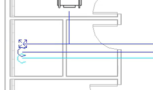
follow the same procedure to create a pipe placeholder for chilled water return,

02:42

changing the elevation to zero at the riser.

02:49

Finally create branch pipes from the main run for chilled water flow and

02:54

for chilled water to return to each of the fan core unit positions

02:59

at a height of 9 ft.

03:05

Quick,

03:05

conceptual mechanical layouts can be created without the

03:09

need to consider final pipe and duct sizes

03:12

associated fittings, final elevations or detailed coordination.

03:20

Although it isn't necessary to set and change elevations while

03:24

creating an early stage layout using duct and pipe placeholders.

03:29

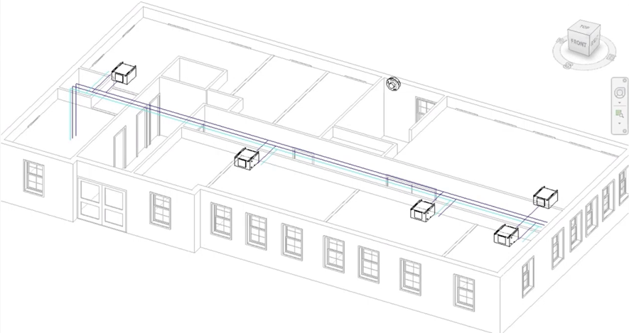
A view of this 3D model can indicate the intentions more clearly.

Video transcript

00:04

At the early stages of an mep project to create a

00:07

detailed mechanical layout can be time

00:10

consuming costly and most likely unnecessary

00:14

with duct and pipe sizes, fittings and detailed coordination.

00:18

Something to be considered at a later stage.

00:22

Single line, indicative mechanical layouts are more usual at this stage.

00:27

Moving to detailed design as the project progresses

00:32

in red,

00:32

this is taken care of by using duct and pipe placeholders,

00:37

duct and pipe placeholders carry the same intelligence as regular duct and pipe

00:41

but are represented by a single line and do not consider details such as fittings,

00:49

duct and pipe placeholders are found on the

00:51

rack panel and the plumbing and piping panel of the systems tab

00:56

ensure the current view is set to H VAC floor plans one mec.

01:03

In this view, the equipment has been placed only as a guide.

01:08

Let's start by creating a duct placeholder,

01:11

select duck placeholder from the ribbon.

01:13

And a review of the type selector shows that even though this is a placeholder,

01:18

the duck type can still be selected

01:21

and from the options bar, the size can be set,

01:24

giving you the option to make an early choice if required

01:28

changing the system type to supply air,

01:31

leave all other options as they are and draw

01:34

a duct run along the center of the corridor

01:36

at a nominal height of 9 ft.

01:39

Then at the riser,

01:41

change the elevation to zero and select apply from the options bar,

01:48

set the elevation back to 9 ft and draw branches to each of the phone

01:53

call units.

01:55

At the last two fan call units, draw a duct placeholder that crosses the main run

02:12

from the plumbing and piping panel. Select pipe placeholder

02:17

and changing the system type to chilled water flow.

02:20

Draw a run along the corridor below the supply duct run

02:24

again at a height of 9 ft.

02:27

Then at the riser change the elevation to zero

02:30

and select apply

02:37

follow the same procedure to create a pipe placeholder for chilled water return,

02:42

changing the elevation to zero at the riser.

02:49

Finally create branch pipes from the main run for chilled water flow and

02:54

for chilled water to return to each of the fan core unit positions

02:59

at a height of 9 ft.

03:05

Quick,

03:05

conceptual mechanical layouts can be created without the

03:09

need to consider final pipe and duct sizes

03:12

associated fittings, final elevations or detailed coordination.

03:20

Although it isn't necessary to set and change elevations while

03:24

creating an early stage layout using duct and pipe placeholders.

03:29

A view of this 3D model can indicate the intentions more clearly.

Was this information helpful?