• Revit

Conceptual to detailed mechanical layouts

Convert duct and pipe placeholder layouts.

Tutorial resources

These downloadable resources will be used to complete this tutorial:


00:04

With traditional workflows.

00:06

Early stage mechanical layouts are sometimes discarded

00:10

as the project moves to detailed design

00:12

and the duct and piping networks recreated to

00:15

suit the requirements of the developing project.

00:19

Rivet duct and pipe placeholders can be used to leverage early stage

00:23

layouts to create detailed mechanical networks

00:26

utilizing and working with existing information.

00:29

Rather than starting over.

00:32

In this example,

00:33

we will review the duct and pipe placeholders already in the project,

00:37

then convert each layout to duct and pipe including fittings

00:41

while making positional changes as necessary.

00:44

We will finish by adding pipe accessories with the option of

00:47

additional duct and pipe accessories to complete the detailed layout.

00:53

Ensure the current view is set to H VAC floor plans.

00:58

One mec

01:01

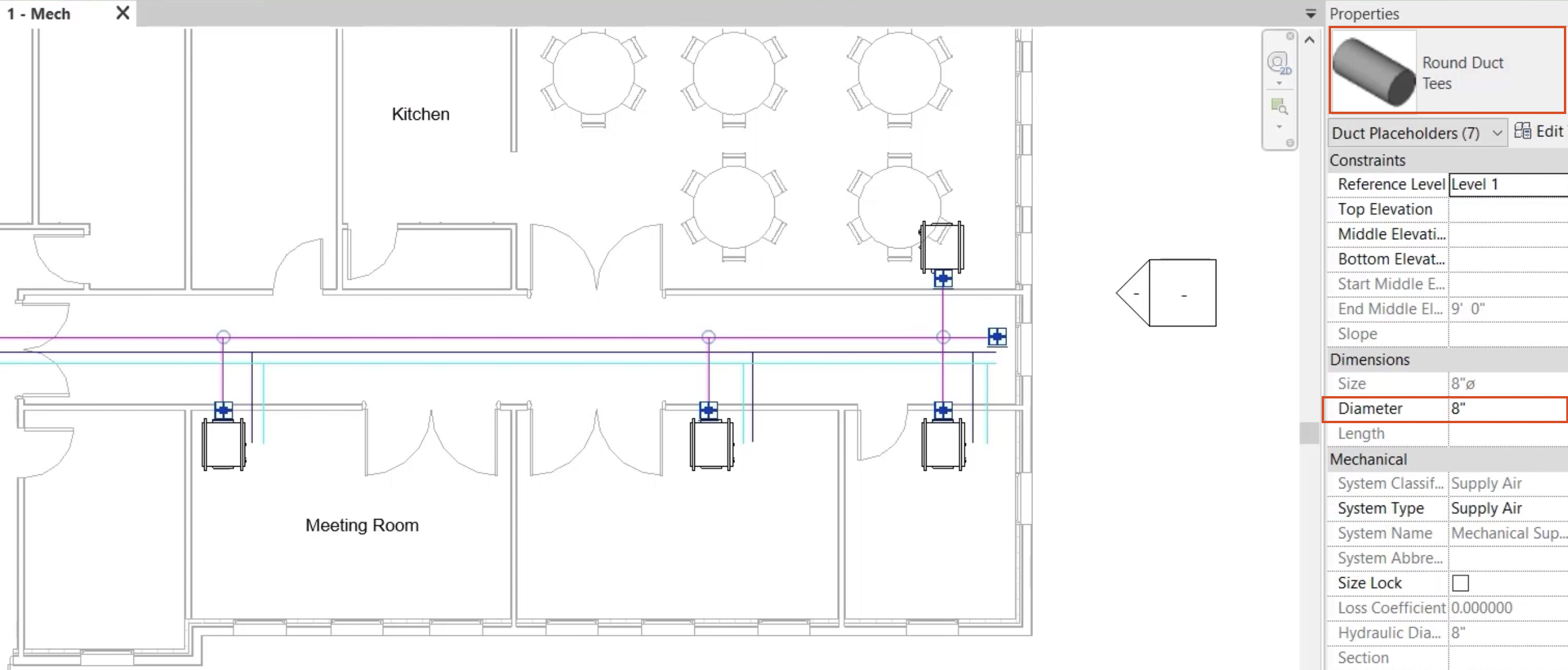
let's start by reviewing the supply duct layout,

01:05

selecting a duct placeholder and reviewing the

01:08

properties shows the duct type size and elevation

01:13

using the tab key from the keyboard. Select the entire system

01:18

once selected use the type selector to change the duck type to round duct with Ts

01:25

and set the diameter to eight inches.

01:30

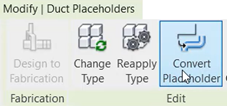
Finally select convert placeholder from the contextual ribbon tab.

01:38

The usual editing tools can now be used to make the necessary adjustments.

01:44

Remove the excess duct from the end of the system

01:50

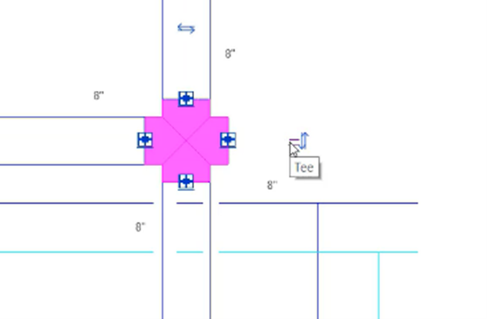
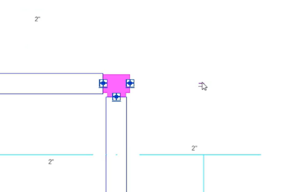
and convert the cross fitting

01:52

to A T.

01:55

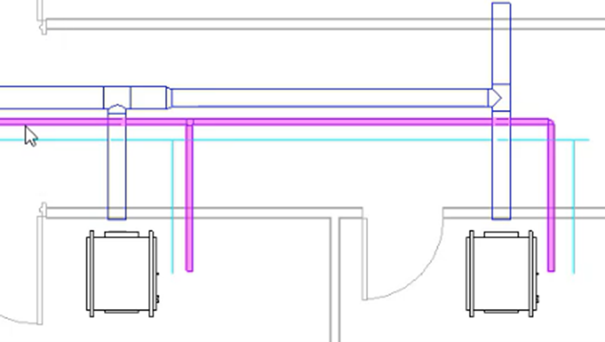
Then from the modify tab of the ribbon,

01:58

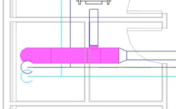
use the split element tool to create splits just after each takeoff along the run.

02:10

Select the first run of duct at the riser

02:14

and set the size to 14 inches.

02:23

Select the second run and set the size to 12 inches

02:34

and the third run to 10 inches.

02:41

Finally select a section of the main rum and

02:45

alter the elevation to 9 ft and four inches.

02:51

Further changes can be made to the duck type by selecting the relevant parts

02:56

of the network and choosing change type from the edit panel of the ribbon

03:00

and making the appropriate selection from the type selector.

03:06

Let's go ahead and convert the chilled water flow piping network in the same way,

03:14

use the tab key to chain,

03:16

select the pipework ensuring the pipework is

03:19

set to carbon steel screwed flange coupling.

03:24

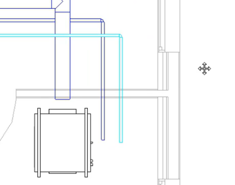
Once selected, choose convert placeholder from the ribbon,

03:30

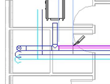
then remove the excess pipe at the end and convert the T to an elbow.

03:38

Finally

03:39

change the elevation for the piping network to 8 ft 10 inches

03:46

and the diameter to one and a quarter inches

03:56

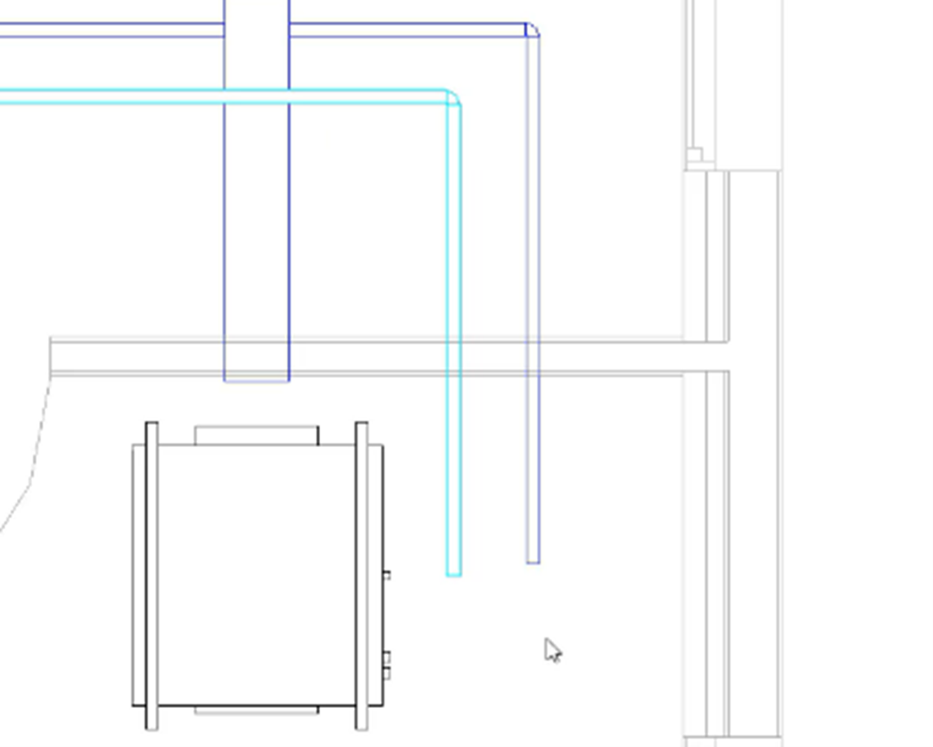
follow the same procedure to convert the chilled water return piping network using

04:02

the same pipe type and setting the elevation to 9 ft nine inches.

04:12

Once converted, the piping networks can be repositioned

04:21

connected to equipment,

04:27

pipe and duct accessories can be added

04:34

and detailed coordination can be carried out,

04:39

finish connecting the remaining equipment to the

04:42

chilled water flow and chilled order,

04:44

return piping networks

04:46

and complete the detailed layout by adding pipe accessories.

04:51

If the details of the design are known at an early stage in a project,

04:55

then duct and pipe placeholders may not have been used

04:58

and a detailed coordinated layout created from the start.

05:02

However,

05:03

where placeholders have been used time can

05:05

be saved by utilizing the original intent

05:08

convert placeholders to duct and pipe

05:11

reposition and connect to equipment, fixtures and air terminals as required.

05:16

And finally add the appropriate duct and

05:19

pipe accessories to complete the detailed layout.

Video transcript

00:04

With traditional workflows.

00:06

Early stage mechanical layouts are sometimes discarded

00:10

as the project moves to detailed design

00:12

and the duct and piping networks recreated to

00:15

suit the requirements of the developing project.

00:19

Rivet duct and pipe placeholders can be used to leverage early stage

00:23

layouts to create detailed mechanical networks

00:26

utilizing and working with existing information.

00:29

Rather than starting over.

00:32

In this example,

00:33

we will review the duct and pipe placeholders already in the project,

00:37

then convert each layout to duct and pipe including fittings

00:41

while making positional changes as necessary.

00:44

We will finish by adding pipe accessories with the option of

00:47

additional duct and pipe accessories to complete the detailed layout.

00:53

Ensure the current view is set to H VAC floor plans.

00:58

One mec

01:01

let's start by reviewing the supply duct layout,

01:05

selecting a duct placeholder and reviewing the

01:08

properties shows the duct type size and elevation

01:13

using the tab key from the keyboard. Select the entire system

01:18

once selected use the type selector to change the duck type to round duct with Ts

01:25

and set the diameter to eight inches.

01:30

Finally select convert placeholder from the contextual ribbon tab.

01:38

The usual editing tools can now be used to make the necessary adjustments.

01:44

Remove the excess duct from the end of the system

01:50

and convert the cross fitting

01:52

to A T.

01:55

Then from the modify tab of the ribbon,

01:58

use the split element tool to create splits just after each takeoff along the run.

02:10

Select the first run of duct at the riser

02:14

and set the size to 14 inches.

02:23

Select the second run and set the size to 12 inches

02:34

and the third run to 10 inches.

02:41

Finally select a section of the main rum and

02:45

alter the elevation to 9 ft and four inches.

02:51

Further changes can be made to the duck type by selecting the relevant parts

02:56

of the network and choosing change type from the edit panel of the ribbon

03:00

and making the appropriate selection from the type selector.

03:06

Let's go ahead and convert the chilled water flow piping network in the same way,

03:14

use the tab key to chain,

03:16

select the pipework ensuring the pipework is

03:19

set to carbon steel screwed flange coupling.

03:24

Once selected, choose convert placeholder from the ribbon,

03:30

then remove the excess pipe at the end and convert the T to an elbow.

03:38

Finally

03:39

change the elevation for the piping network to 8 ft 10 inches

03:46

and the diameter to one and a quarter inches

03:56

follow the same procedure to convert the chilled water return piping network using

04:02

the same pipe type and setting the elevation to 9 ft nine inches.

04:12

Once converted, the piping networks can be repositioned

04:21

connected to equipment,

04:27

pipe and duct accessories can be added

04:34

and detailed coordination can be carried out,

04:39

finish connecting the remaining equipment to the

04:42

chilled water flow and chilled order,

04:44

return piping networks

04:46

and complete the detailed layout by adding pipe accessories.

04:51

If the details of the design are known at an early stage in a project,

04:55

then duct and pipe placeholders may not have been used

04:58

and a detailed coordinated layout created from the start.

05:02

However,

05:03

where placeholders have been used time can

05:05

be saved by utilizing the original intent

05:08

convert placeholders to duct and pipe

05:11

reposition and connect to equipment, fixtures and air terminals as required.

05:16

And finally add the appropriate duct and

05:19

pipe accessories to complete the detailed layout.

Was this information helpful?